Gerv Wright continues his series on valve design for 16mm locomotives
Jubilee 1897 at Moss Bank
SIMPLIFIED INSIDE WALSCHAERTS VALVE GEAR PART 2
In this part, I’ll cover the construction of the inside motion for my model of Manning Wardle, works no 1382, ‘Jubilee 1897’. The drawings I used were by Stuart L Baker and were published in Narrow Gauge & Industrial Modelling Review, Issue 120. My version of the locomotive is in its original Penrhyn condition, i.e. before Penrhyn replaced the saddle tank (different profile and mounted higher).
- Why Walschaerts for the inside motion
- Design for the model
- Some construction notes
- Timing
- Why Inside Walschaerts
The original loco was built with inside Stephenson’s motion and to drive the motion, eccentrics are used on the drive axle. Stephenson and other variations like Gooch or Allen require two eccentrics for each side of the loco – one on each side for forward and reverse.
Inside Walschaerts has the advantage of only requiring one eccentric per side. In model form it is much easier to manufacture and fit two eccentrics compared to four in the space available on the drive axle. As most of the motion is hidden between the frames, for me, the practical considerations outweighed fidelity to the original. I, therefore, chose to design a form of simplified Walschaerts for my model of the Manning Wardle ‘Jubilee 1897’.
- Design for the model
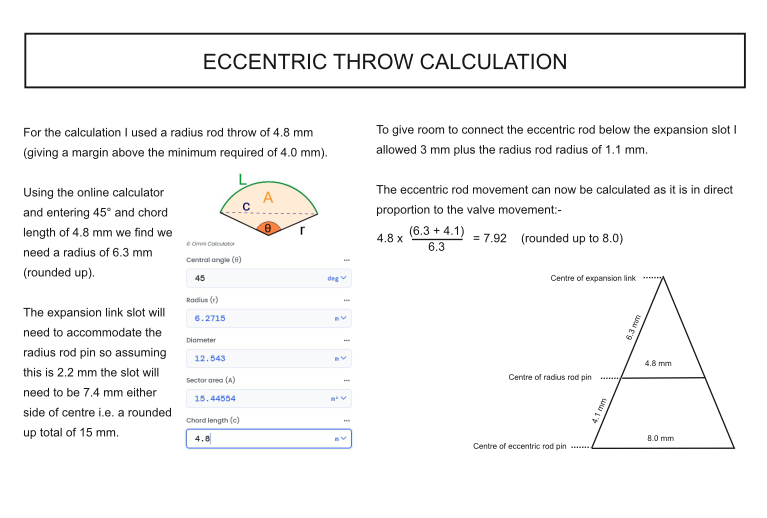
As I made the cylinders and valve chest, the design for the motion needs to start here. I compared designs from Brian Wilson, Keith Bucklitch & Roundhouse (see bibliography). Although broadly similar to each other, I chose to use Brian Wilson’s measurements. These provided a valve with a lap of 0.4 mm and requires a minimum valve travel of 4 mm.
Hopefully the diagrams will provide some clarity.
The calculation from then on is identical to that outlined for outside motion in Part 1.
Firstly, we need to calculate the expansion link length and thereafter the amount of throw our eccentrics need to provide.
- Some construction notes
As in Part 1, this is not intended to be a comprehensive guide to the build but a view of those areas that may be of interest.
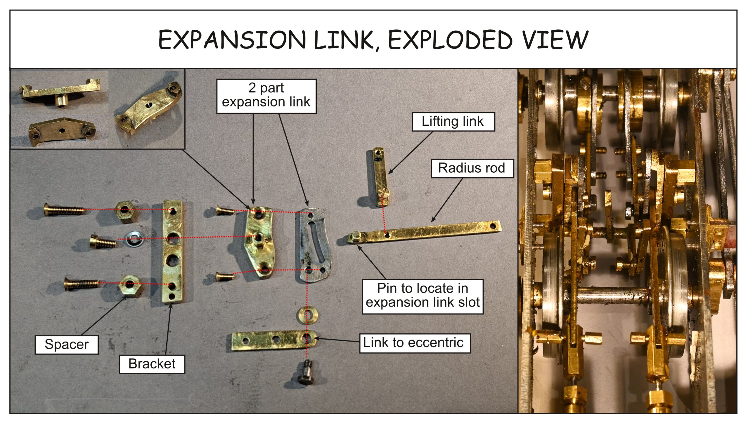
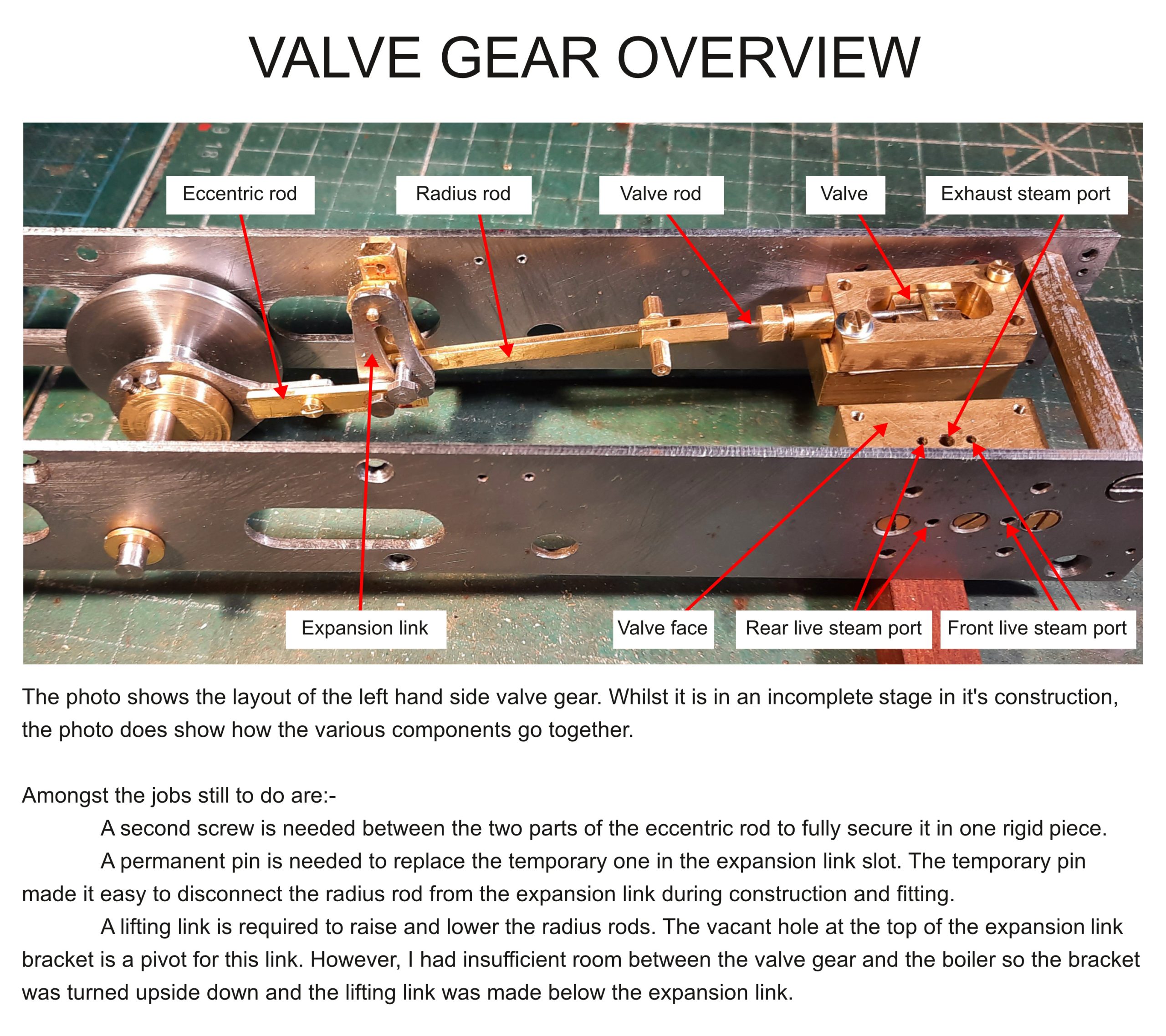
The radius rod length was measured by superimposing the motion onto the side view drawing of the locomotive. It was made to be as long as possible bearing in mind that it must fit above the lead axle. The length of the radius rod determines the radius of the expansion link slot.
The expansion link was again made in segments, but this time screwed together and having only one pivot.
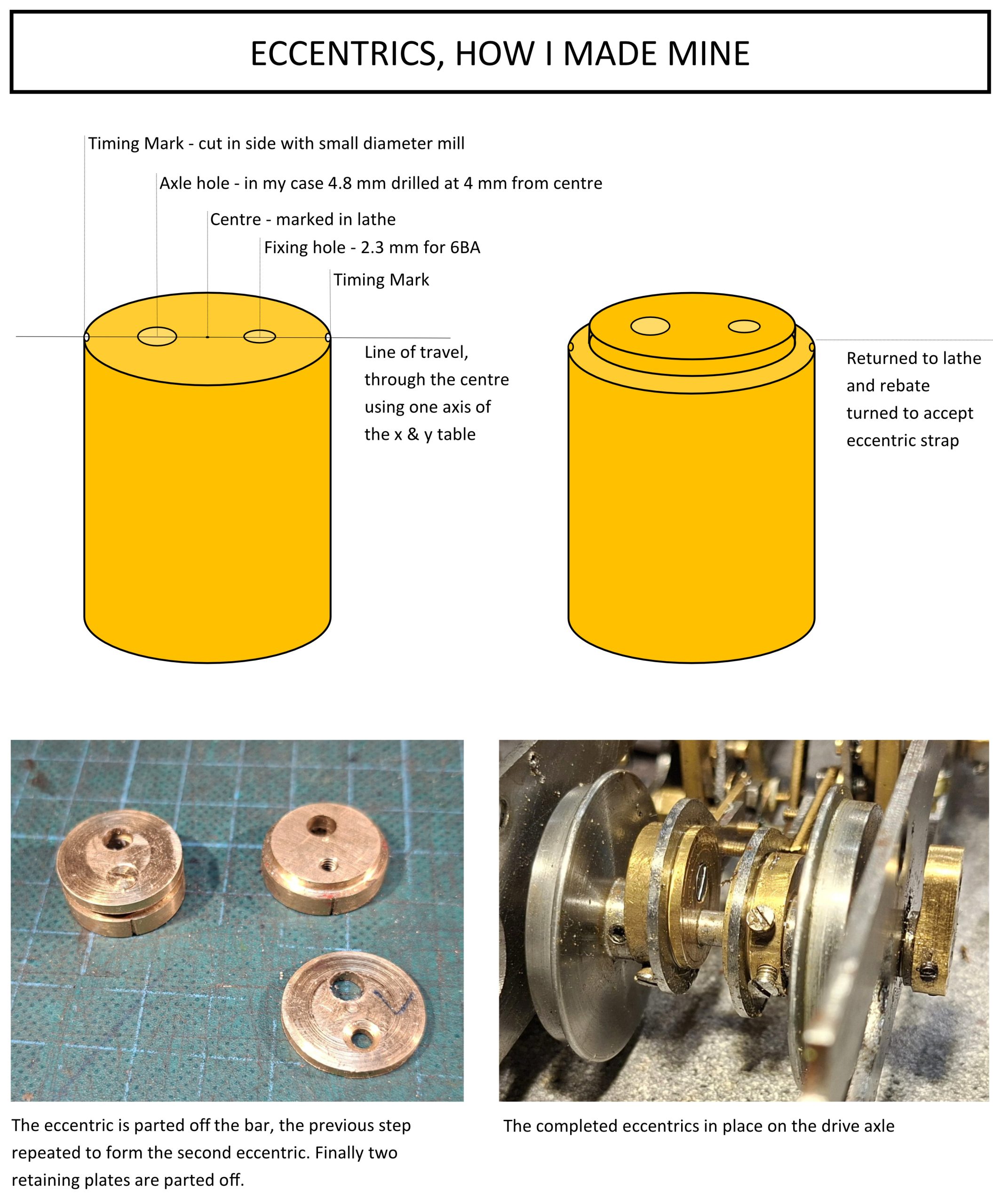
The eccentrics were made from one piece of round bar first centre marked on the lathe and then drilled on the milling machine using one axis of the x & y table. The edges were marked in the same plane with a milling cutter to provide a timing mark. The rebate on the first eccentric to take the eccentric strap was then machined on the lathe and then parted off. The process repeated for the second eccentric and then finally two plain retaining plates were parted off.
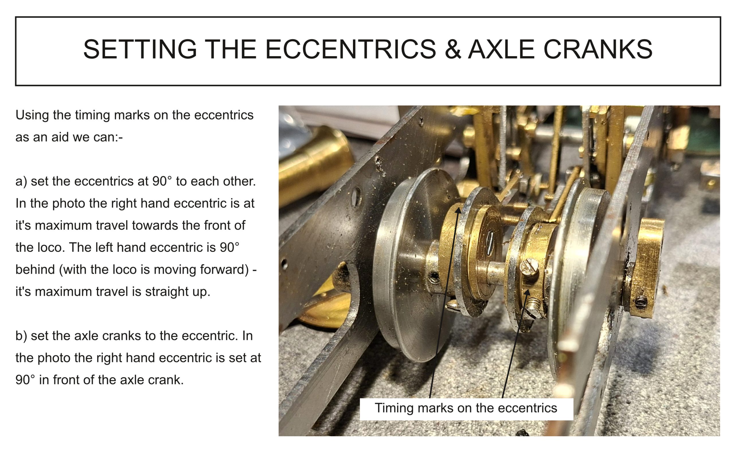
With the eccentrics and axle/wheel cranks in the correct place the valves can now be timed. As with the outside design, the valves were centred on the valve face by comparing and adjusting their maximum forward and backward movement (which should occur with the wheel cranks at forward and bottom dead centre). Again, this was done with valve gear set firstly in forward and then in reverse with the wheels turned in the appropriate direction. A small amount of compromise will probably be needed.