
Roy Plum leads us through the intricacies of fitting speed, sound ,lights, and much much more into our battery locos.
Introduction
I have to admit up front, when I first heard the sound effects available via DCC control for 4mm scale modellers, I was green with envy. If only the 16mm garden railway fraternity had access to a similar system. I know that there are various providers of sound cards to install in our 16mm locos, but they didn’t seem to offer anything like the range of sounds available to the 4mm scale people. What’s more, they seemed quite expensive.
Thus I read with great interest that Hornby had brought out a DCC chip that didn’t rely on digital commands through the track. Their new (in 2023) HM7000 DCC chip could be controlled via Bluetooth from a smart phone or tablet. This seemed to offer everything I’d imagined. I should be able to power the chip up from a standard set of 12v batteries and control speed, direction, lights, sounds and any other features on an electric loco from my phone.
Nothing ventured, etc… so in 2023 I ordered an HM7000 21 pin chip for around £70 and awaited delivery.
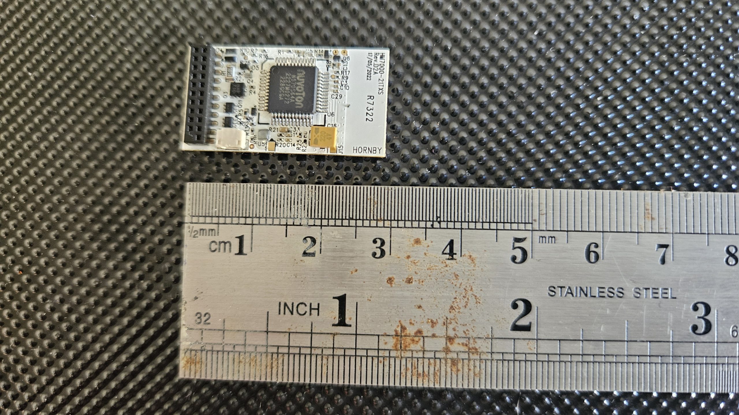
When it arrived, the first thing I noticed was how small the chip actually is. Photo 01 shows the chip alongside a ruler. They are tiny, and when you think that this one chip controls speed, direction, lights, sounds and (as they say) much, much more… it’s quite incredible.
Having parted with my “hard earned” I didn’t want to damage the chip, and I was aware that static electricity from your hands can actually destroy a chip. Up to now this hasn’t happened to me…. I can find much more impressive ways to destroy these chips.
I have read that it’s a good idea to earth yourself so as to allow any static that has built up on your person to drain way to ground. One way to do this is to touch the metal screw head on a mains electricity socket in your home. If you don’t understand what I’m describing, then please don’t experiment!!! Also probably best to avoid wearing that acrylic jumper you were gifted last Christmas when you’re working with microchips.
CONNECTING THE DCC CHIP TO OUR ELECTRIC LOCO
So, we have the chip…. How do we connect up to it? What we need is a break out adaptor. These things cost around £4 each and are readily available from the web. Search for 21-Pin DCC Breakout Adaptor.
The Photo below shows one of the adaptors I bought.
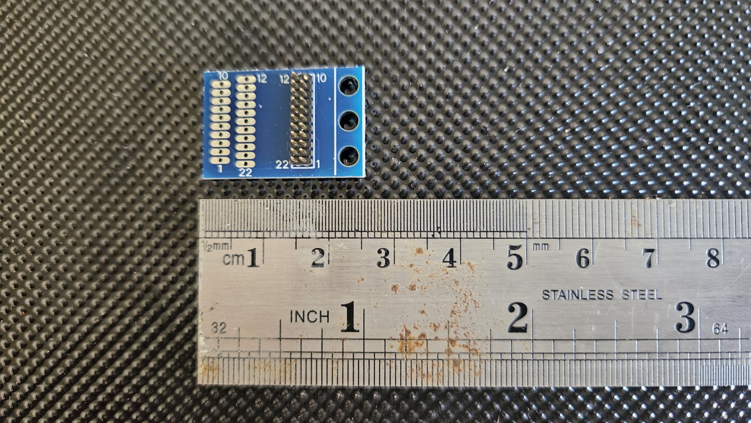
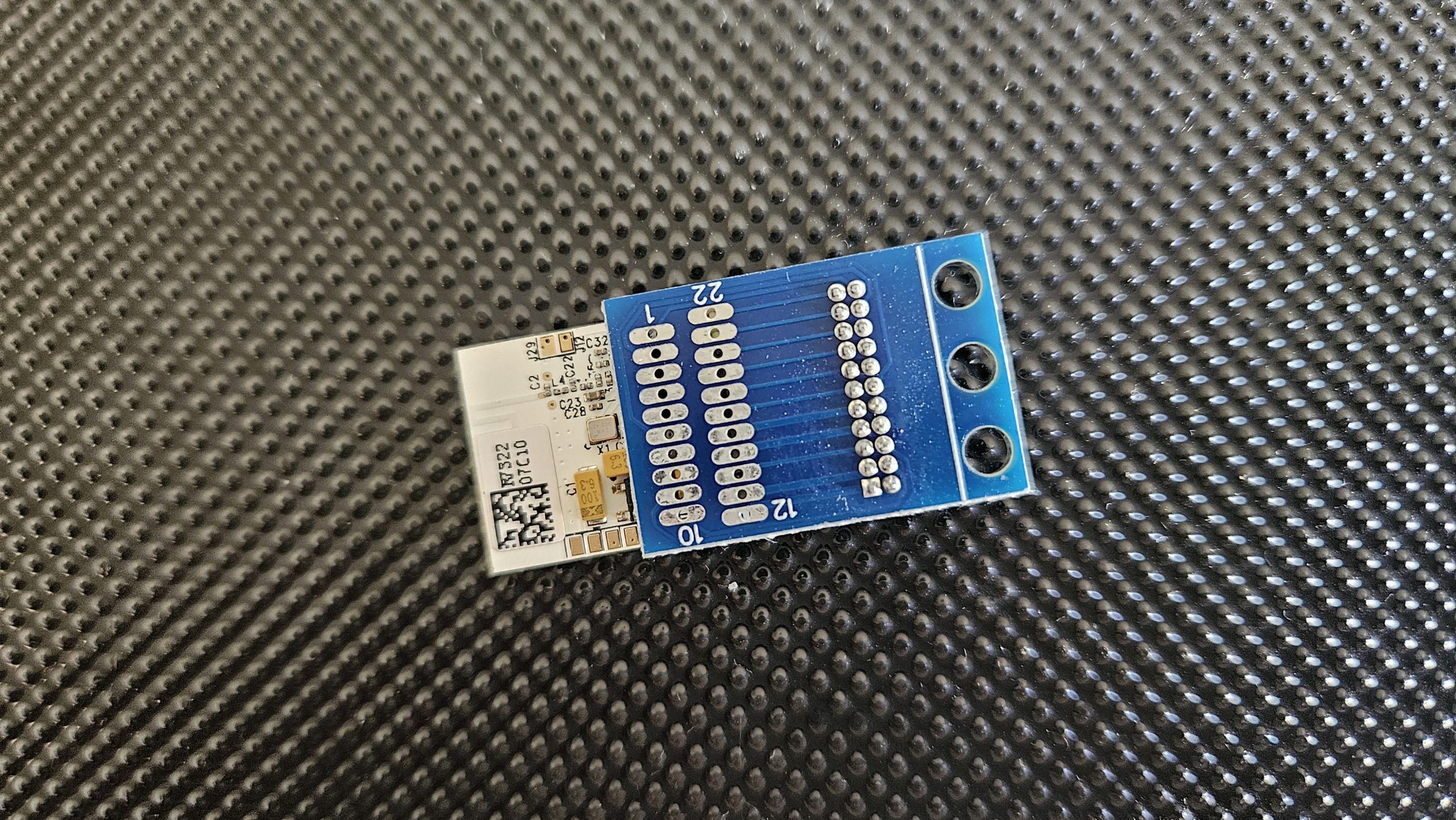
The HM7000 chip has 21 very small pins on it, sitting in 2 rows (11 pins and 10 pins). The missing 11th pin in one of the rows ensures that you insert the chip into a matching socket the right way around. The breakout adaptor consists of a 21 pin socket with printed circuit links connected to 21 solder pads. In fact, on the breakout adaptors I used there are 21 solder pads on either side of the board… so you can decide which way up you’re going to have it when you “piggy back” the DCC chip onto it. Photo 03 shows the HM7000 DCC chips mounted on the breakout adaptor.
Mounting the chip is a case of gently aligning its 21 pins (which are very, very fine,) with the 21 holes in the Breakout Adaptor. A magnifying glass and steady (static free) hands are required until you get used to the process, after which it’s quite easy.
To get our loco to “see” the chip, we have to connect the relevant wires in the loco to the 21 solder pads on the Breakout Adaptor… but which wire goes where?
(I’m tired of typing Breakout Adaptor, so let’s just call it the BA from now on).
The BA is likely to have very tiny writing on it indicating which solder pad does what. If you’ve bought from a reputable supplier (ie paid a little more and avoided e-bay) they might even have sent you some paperwork with the BA telling you which pad does what. The information is also available on the web. For instance, see
21-Pin to 8-Pin Decoder Adaptor Board (Wired DCC Harness with NEM652 8-Pin Plug)
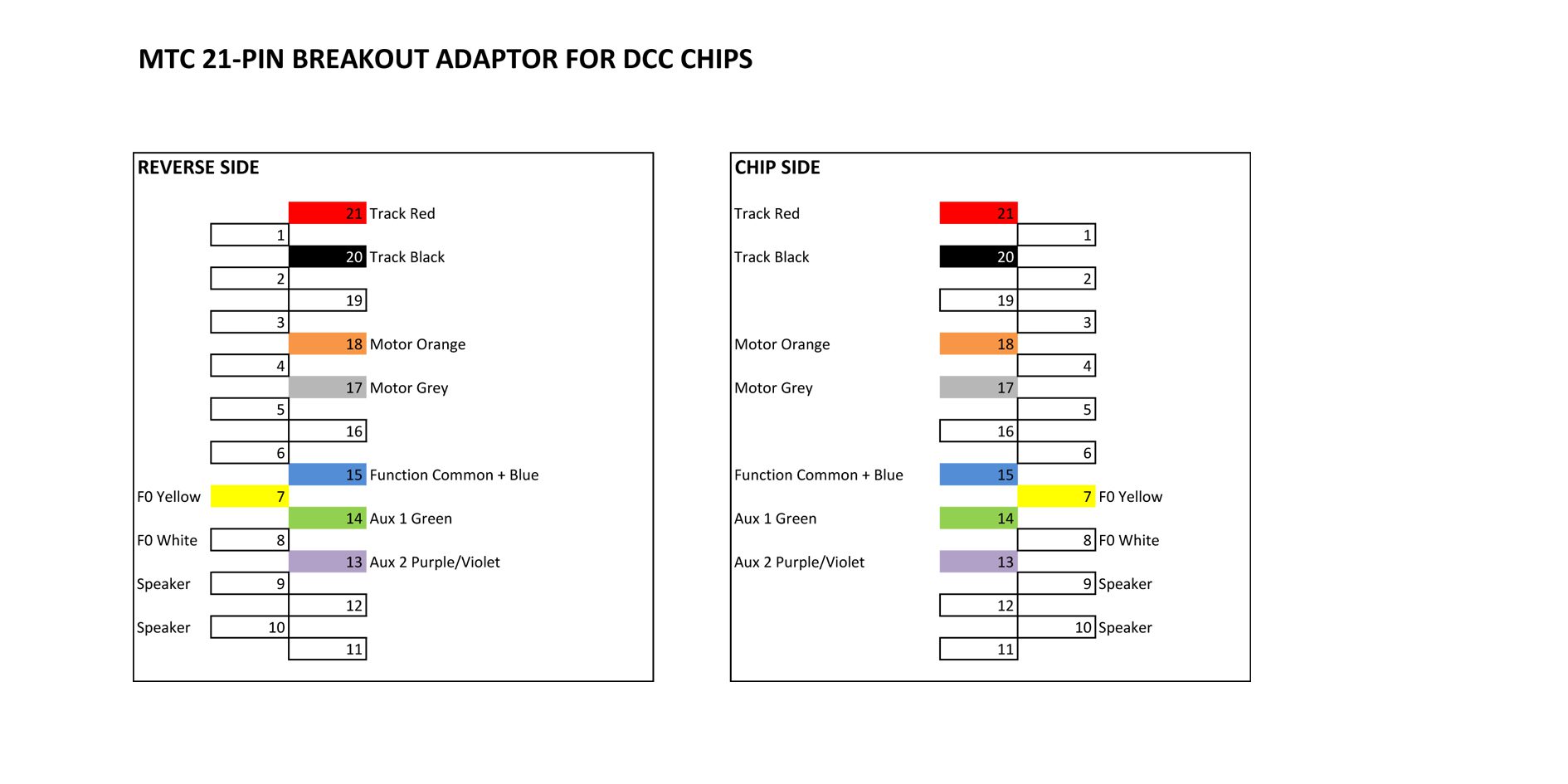
I decided to make my own “map” up, telling me what to connect to where. I also made a mirror image of the “map” so I could solder the connections on the underside if I wished.
Here’s my “map” of the connections.
WIRING UP THE BREAKOUT ADAPTOR
Let’s start connecting the adaptor board to our loco. This is best done with the DCC chip removed…. We don’t want to damage the chip and we want the best possible access to the BA.
I held the BA carefully in a large foldback clip while I worked on it.
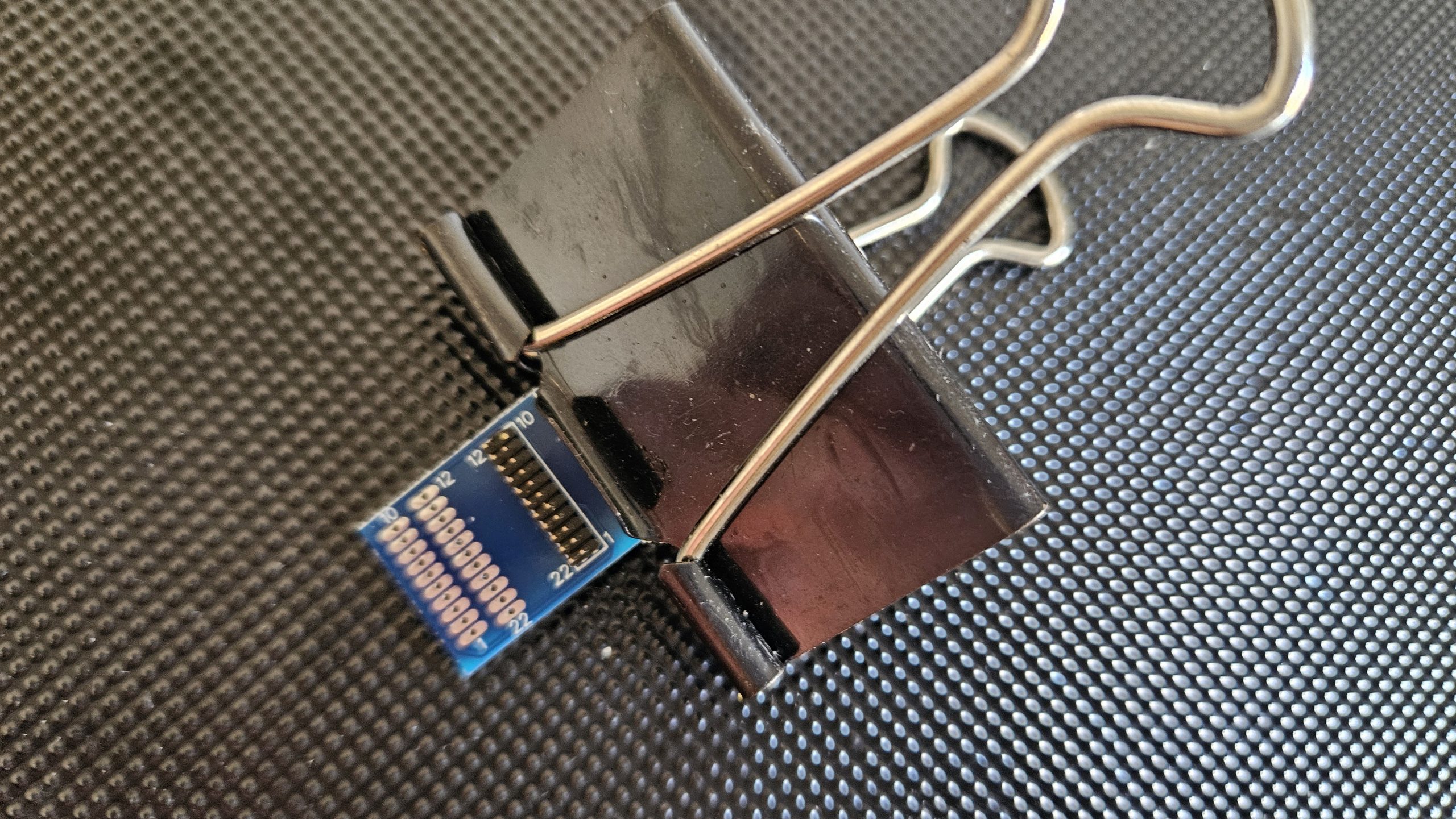
I find that this adds weight and stability to the BA as I get cracking with the soldering iron. An iron with a fine tip is essential… this is very fine, demanding work. A supply of fine wire in several colours is also useful.
Examining our “map” we see that pin 21 is TRACK RED and pin 20 is TRACK BLACK. This is where we supply power to the chip, so instead of connecting it to our track, we connect it to our 12v DC battery pack. Red to positive, Black to negative. (If this comes as a surprise, I suggest you get help from someone else from this point on!).
The Hornby HM7000 chip will operate on DC voltages up to 27v. This and a lot, lot more information is available in the HM7000 manual. It’s 166 pages long and can be downloaded from
https://uk.hornby.com/hm7000/hm-dcc-guides
This website is essential reading for anyone wanting to really understand and experiment with the Hornby DCC system.
In practise, I found the chip worked fine powered by an 11.1v LiPo battery pack. A 14.4v LiPo pack would be even better. 12v NiMH cells should also be fine.
Having got power into the chip, we need it to control our loco’s functions. Let’s start with making the loco move. For this we need to solder the 2 wires from our motor to pins 17 and 18. If we get the wires the wrong way around, the loco may not move in the “right” direction. Quite what is the “right” direction depends on your own preference! If it’s a steam outline electric loco then I imagine most of us would say the loco is going forwards when the smokebox is leading. If the direction is “wrong”, just switch the wires around.
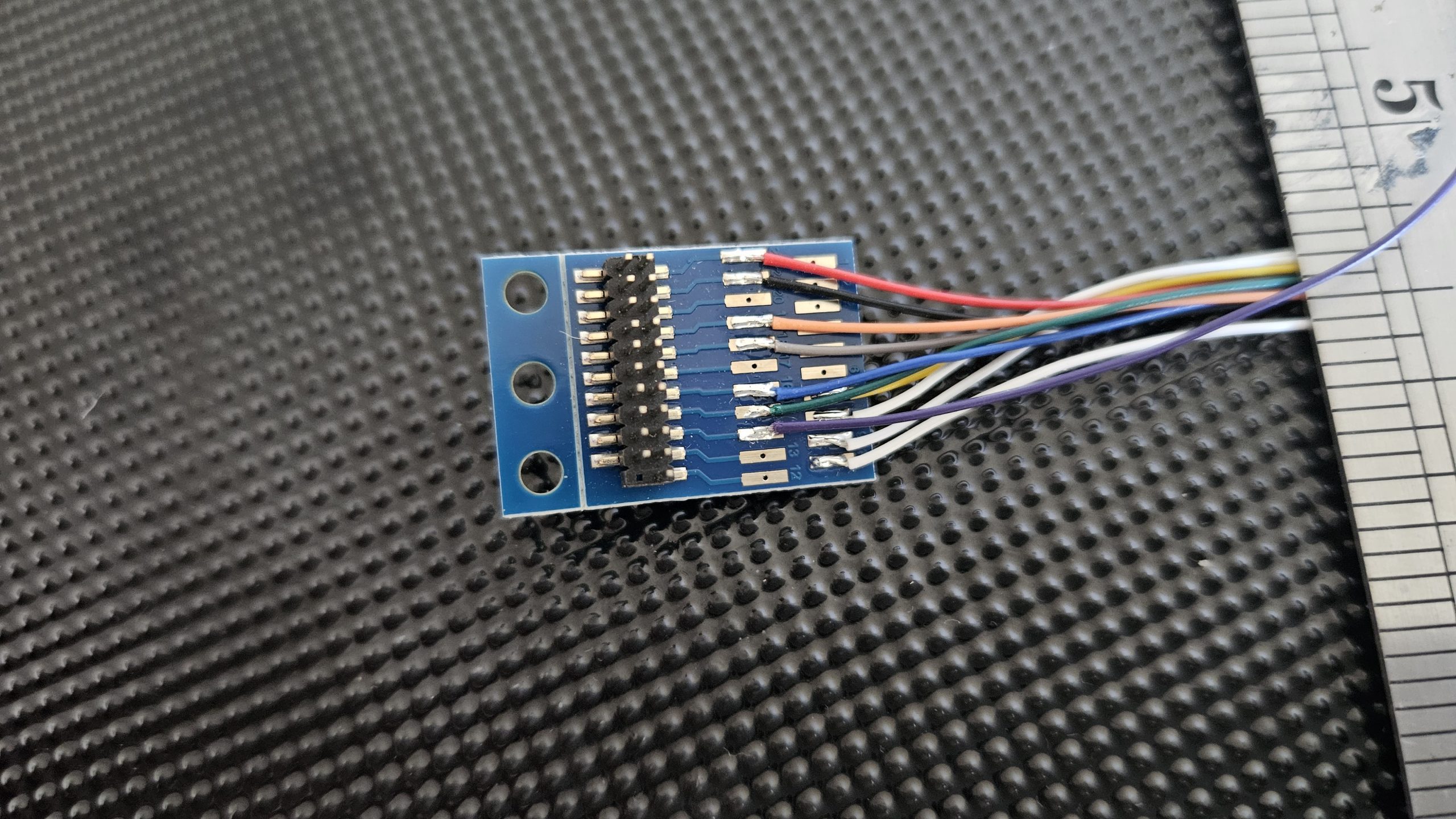
If soldering fine wires is not your “thing”, then you can buy BAs with all the wires pre-soldered to the pads. See Photo 06
Adding Sound
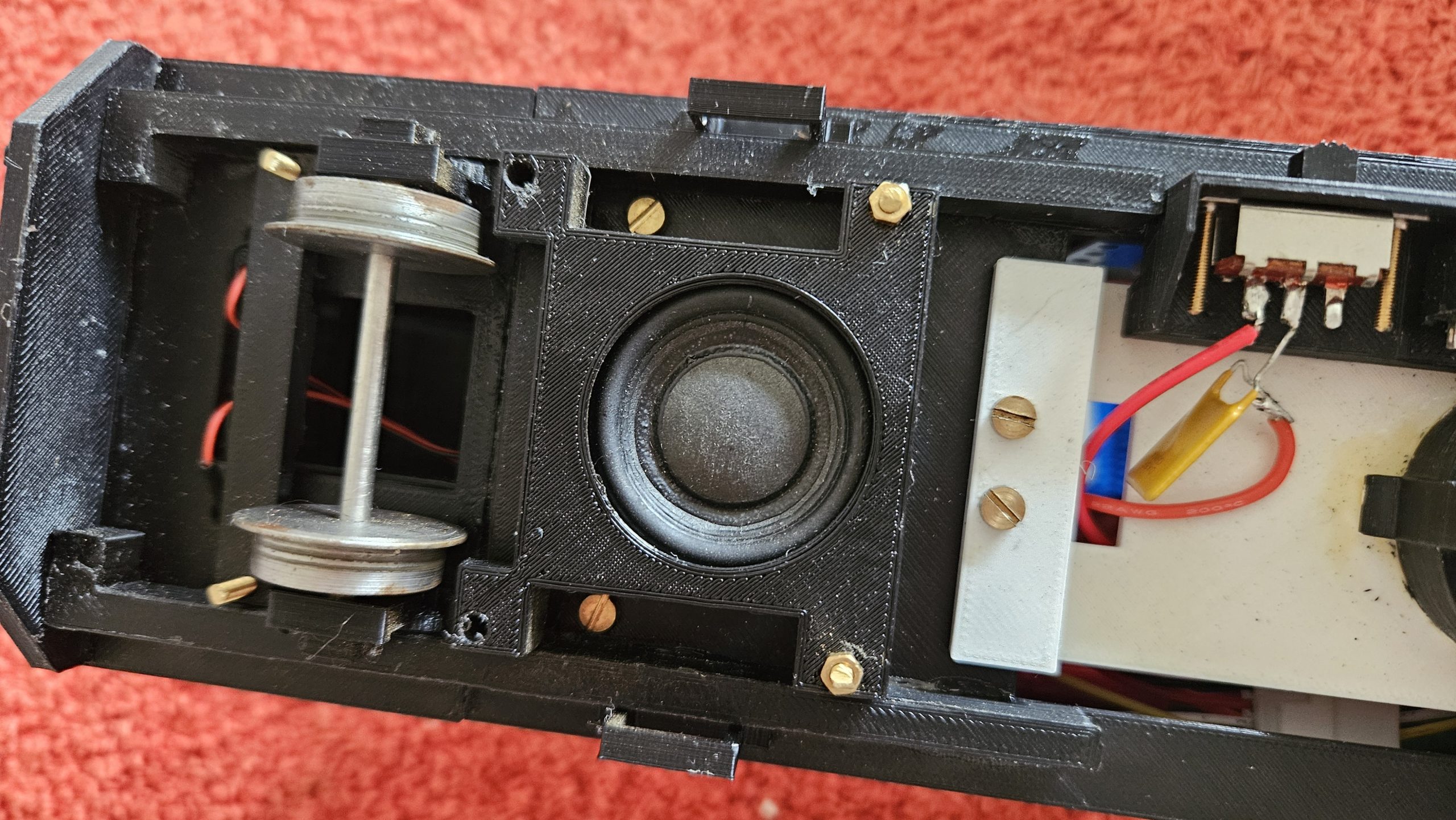
What else? Shall we have some sounds? This is pretty simple… Wire an 8 ohm speaker to pads 9 and 10 and you’ll have sound. The size and shape of the speaker is your choice…. You can have anything from a small “sugarcube” type speaker to something 3 or even 4 inches across (if your loco has the space for it!). The important thing is that the speaker must be rated at 8 ohms resistance, or you’ll probably damage the DCC chip.
The photo below shows a typical speaker mounted in my railbus.
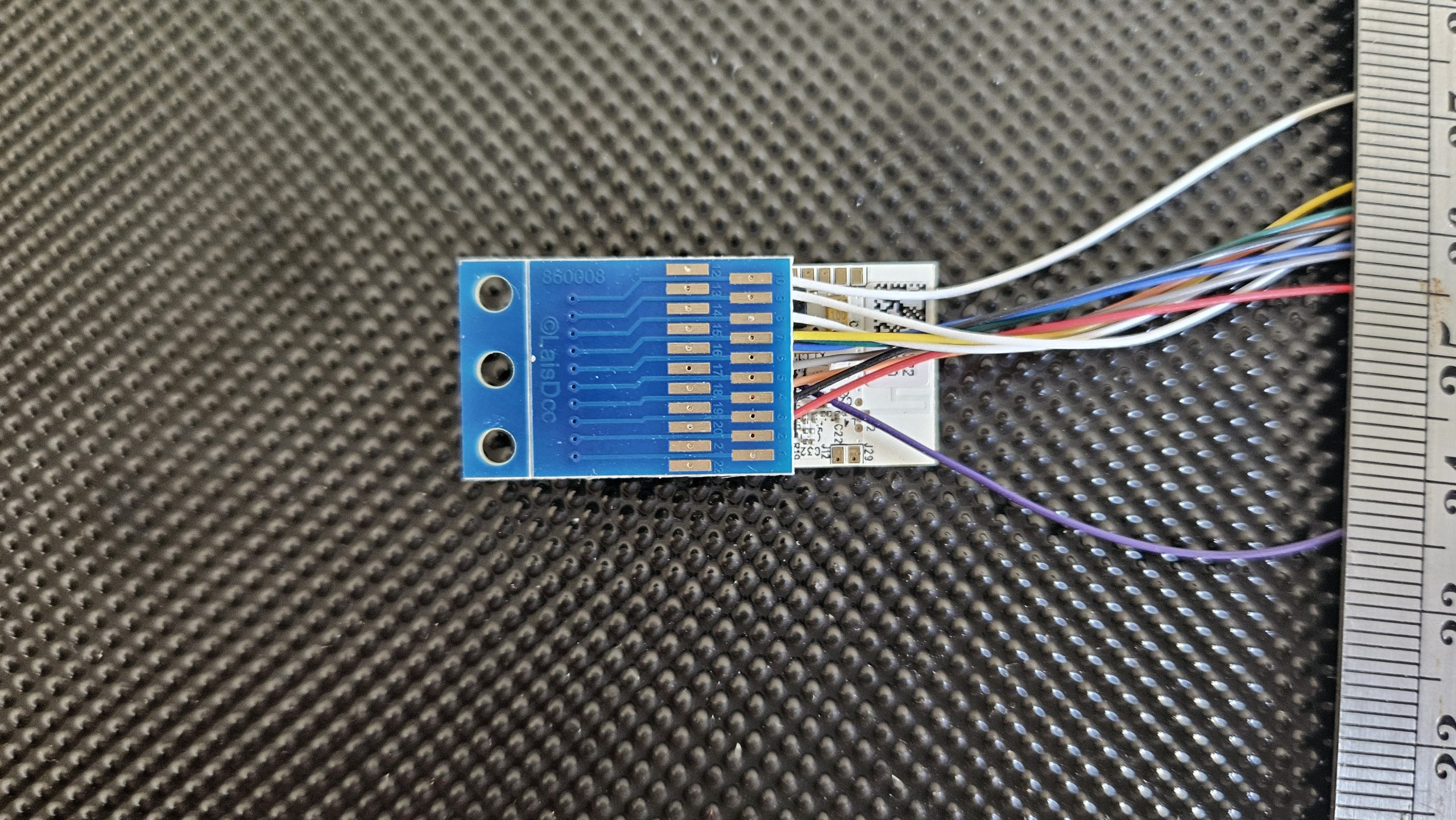
I also try to wire from the BA to the loco via a small multi-pin connector. This allows me to work on the electrical “gubbins” away from the loco and to connect it in place fairly easily when all the soldering is done (and tested!). When something doesn’t work as expected, it’s then an easy matter to remove the chip and BA from the loco to inspect it and fault find. Usually the fault is down to me soldering to the wrong pad on the BA or allowing solder to creep across to an adjacent pad. Both situations are to be avoided at all costs. Make an error and you’ll see a small amount of smoke rising from your expensive chip, after which nothing will work and the chip is for the bin. I have that Tee shirt.
The next photo shows the BA wired up and the DCC chip piggy backed onto it.
How about controlling some lights?
This is a bit more advanced as you can use a “function” or an “aux” connection. You need to read the manual do get the full details, but basically Function 0 is accessed by soldering a wire to pin 7 or pin 8 and this will send a small current of electricity (100mA max) to something like LED lights. The return wire is soldered to pin 15 and the supply is 14v DC. Don’t forget to put a resistor into the circuit to match the colour of your LEDs. If in doubt, ask someone who is confident about these things. An “aux” connection can be used to switch a relay or other component. The “aux” connection is via pins 13 or 14 with the return being pin 15. In fact, the “switched negative” system is used. This means that pin 15 is positive and live all the time. Pins 7, 8, 13 and 14 are the negative and are switched on and off by the DCC chip.
WARNING!! I did a lot of experimenting to find out how to connect all this up and burned out 2 chips in the process. Take great care and read and understand the manual. I take no responsibility for any loss incurred by anyone who is reading and following the information in this article!!!
INSTALLING AND USING THE APP ON YOUR PHONE OR TABLET
Now that we’ve installed the “hardware” in our loco, to use the DCC chip to control our garden railway electric loco we need the Hornby app on our phone or tablet.
You get the app just as you would any other app. In my case I have an android phone and I use the App Store. Full instructions are provided with the chip itself.
It’s a process that has three stages…..
Stage 1… Download and install the App.
Stage 2… Link the app to the DCC chip in your loco (the chip is called “The Decoder”).
Stage 3… Choose a name for your loco (eg Railbus No1) and download /install the “Sound Profile” you think most appropriate.
Incidentally, with this App on your phone you can repeat stage 3 for several locos and control them all from your phone, but you can only control one at a time while the rest continue to do whatever you last instructed them to! How many locos can you store on your phone or tablet?? I haven’t found a definitive answer, but the internet suggests that this is related to the capabilities of your phone or tablet. Evidently, some people have stored the profiles of up to 60 locos.
Sound Profiles
Hornby call the set of sounds and related actions appropriate for each loco a “Profile”, and there are a lot to choose from. Unfortunately, none are narrow gauge prototypes so you have to choose whatever you think best! I installed the profile for the BR Class 37 diesel in my railbus. I thought it sounded better than an Intercity 125.
To see all the different profiles currently available, go to
https://d63oxfkn1m8sf.cloudfront.net/1717/6096/3900/Available_Profiles_for_HM_DCC_14-10-2025.pdf
So what can you do in this the App?
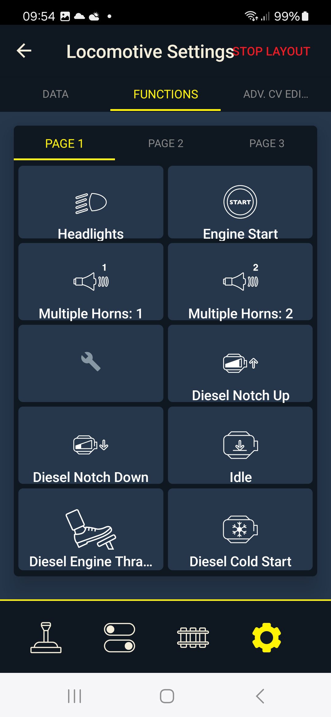
In the case of my railbus, I have directional control and speed, inertia, headlights on/off, engine start/stop/running/thrash(!)/cold engine start, several BR type horns, guards’ whistle, door slam, flange squeal, buffer clang, brakes and much, much more (as they say). To be honest, you’re going to be very annoying to everyone else running trains alongside you so it’s probably best to drive your loco with normal engine sound and the odd toot on the horn. You can just be smug in the knowledge that you have “much, much more” up your sleeve.
Looking at the available profiles at the time of writing (March 2026) the most useful ones might be:
SD009 BR Class 08 shunter
SD013 BR Class 37
SD029 Black 5
SD054 Class 2MT
SD056 Lion steam loco
….but if you want your shunter to sound like a Deltic, why not?
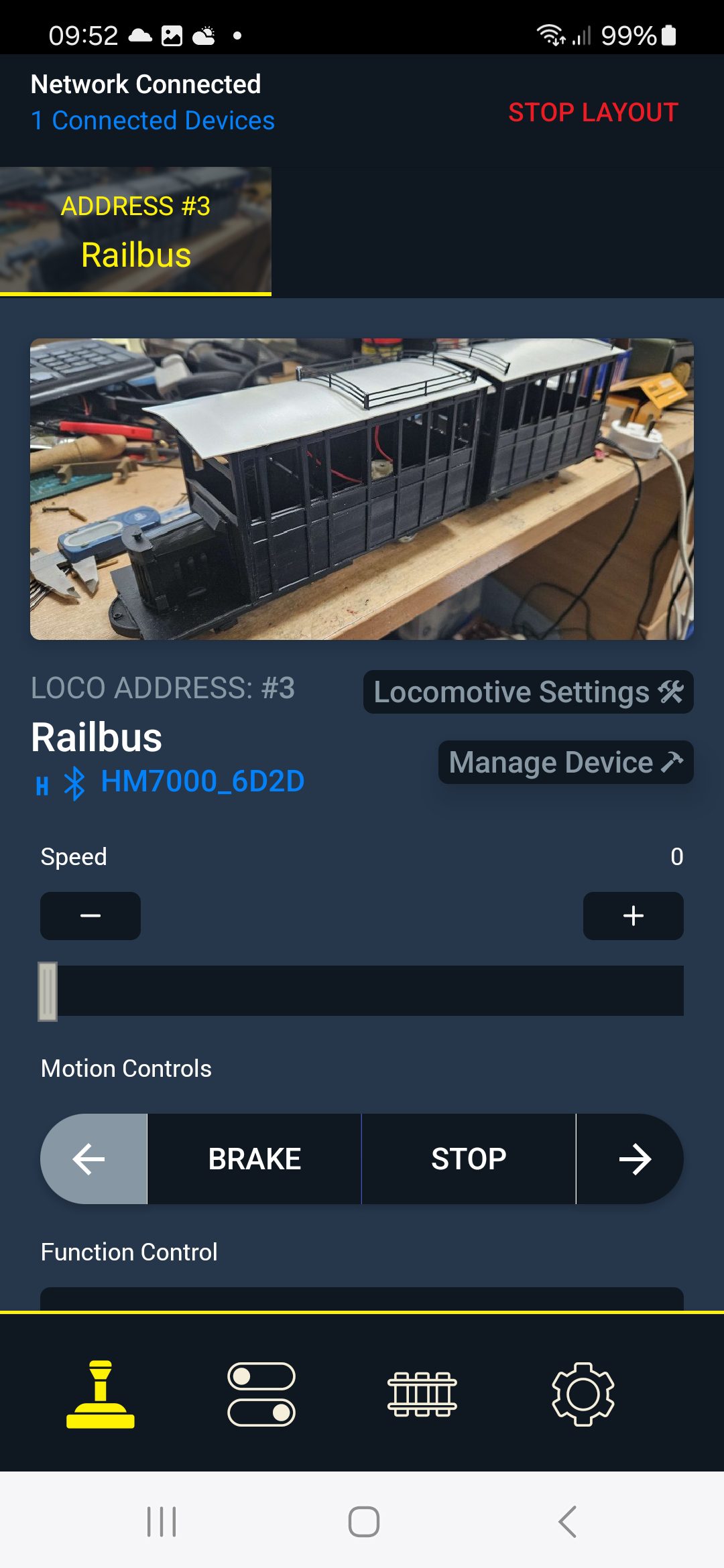
Here are some images of the App interface you’ll see on your phone or tablet
App interfaces
Normal loco operating screen
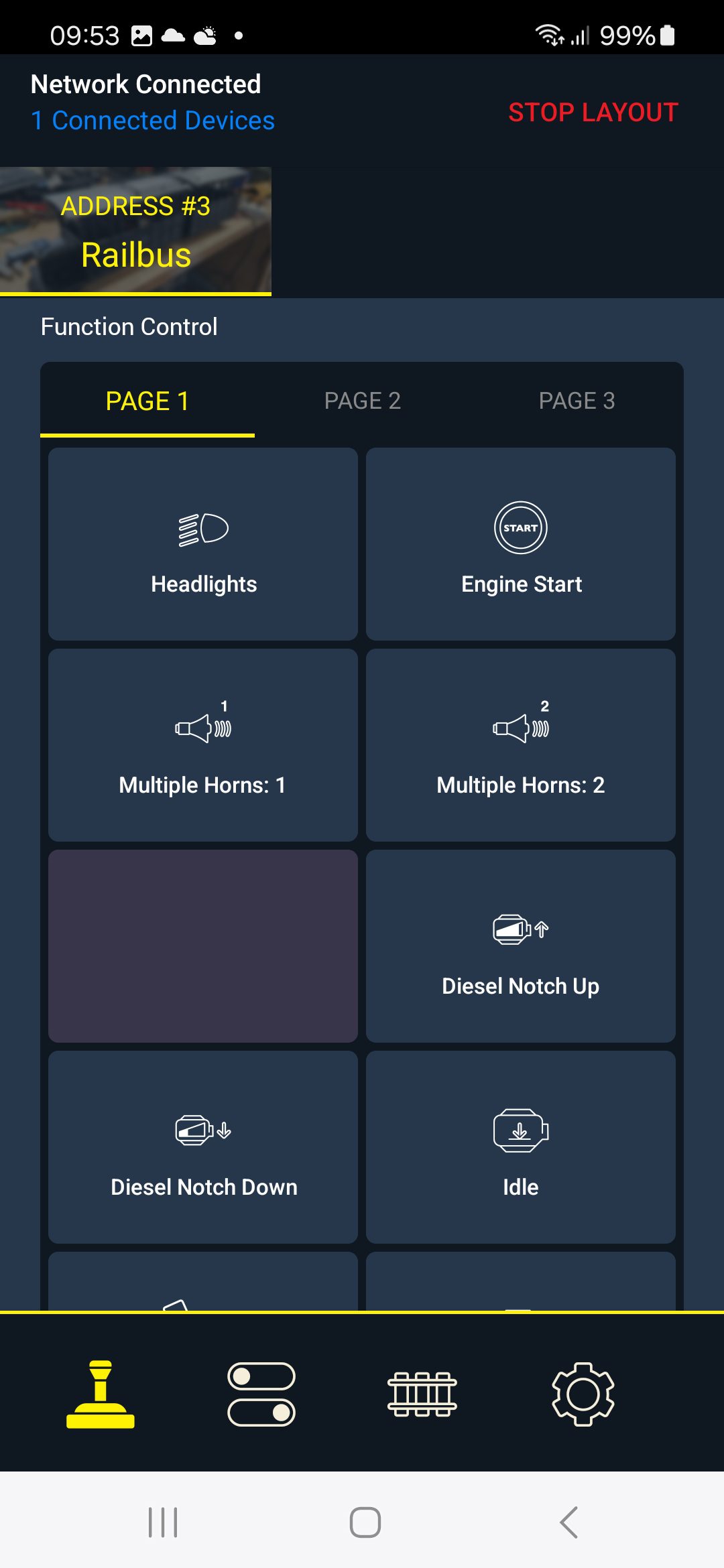
Sound effects page 1 (10 individual sounds)
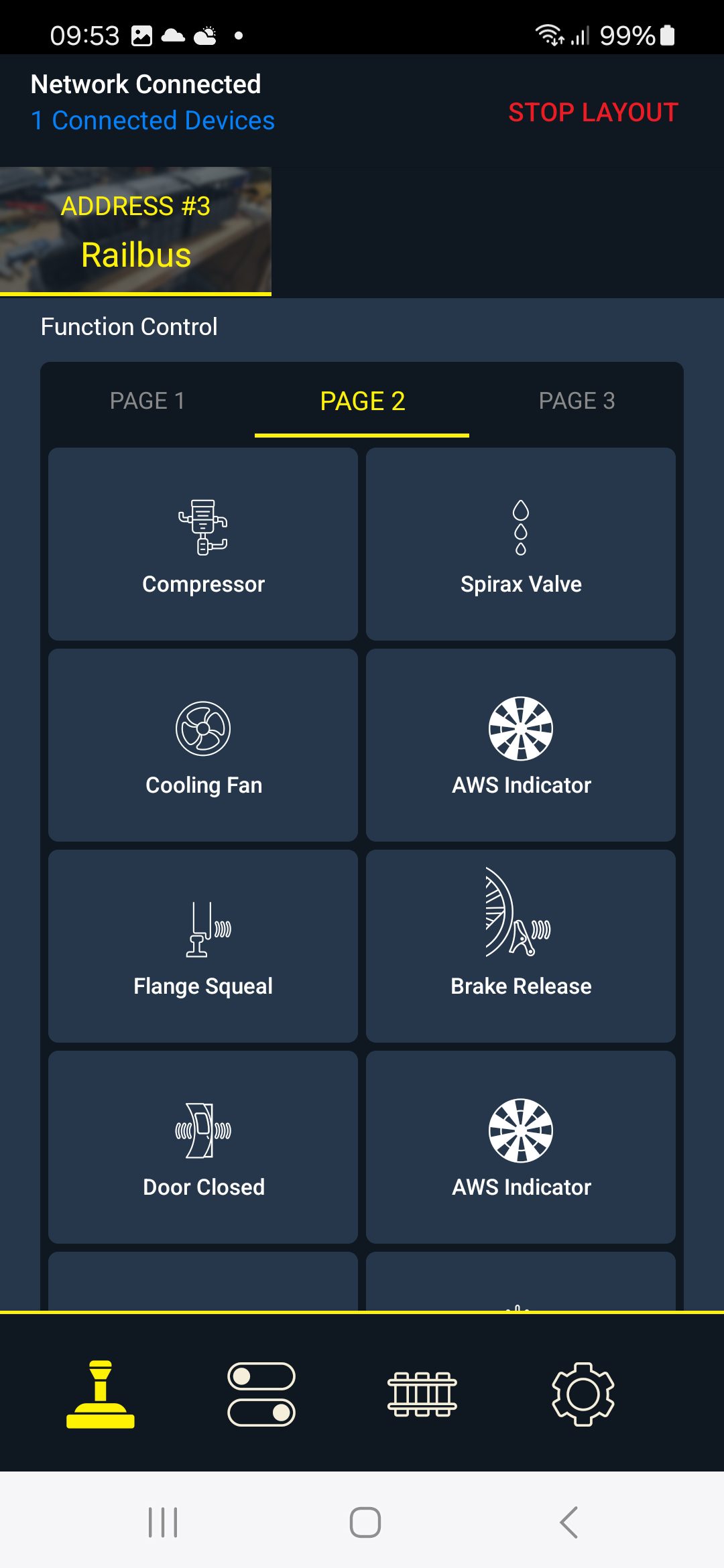
Sound effects page 2 (another 10 sounds)
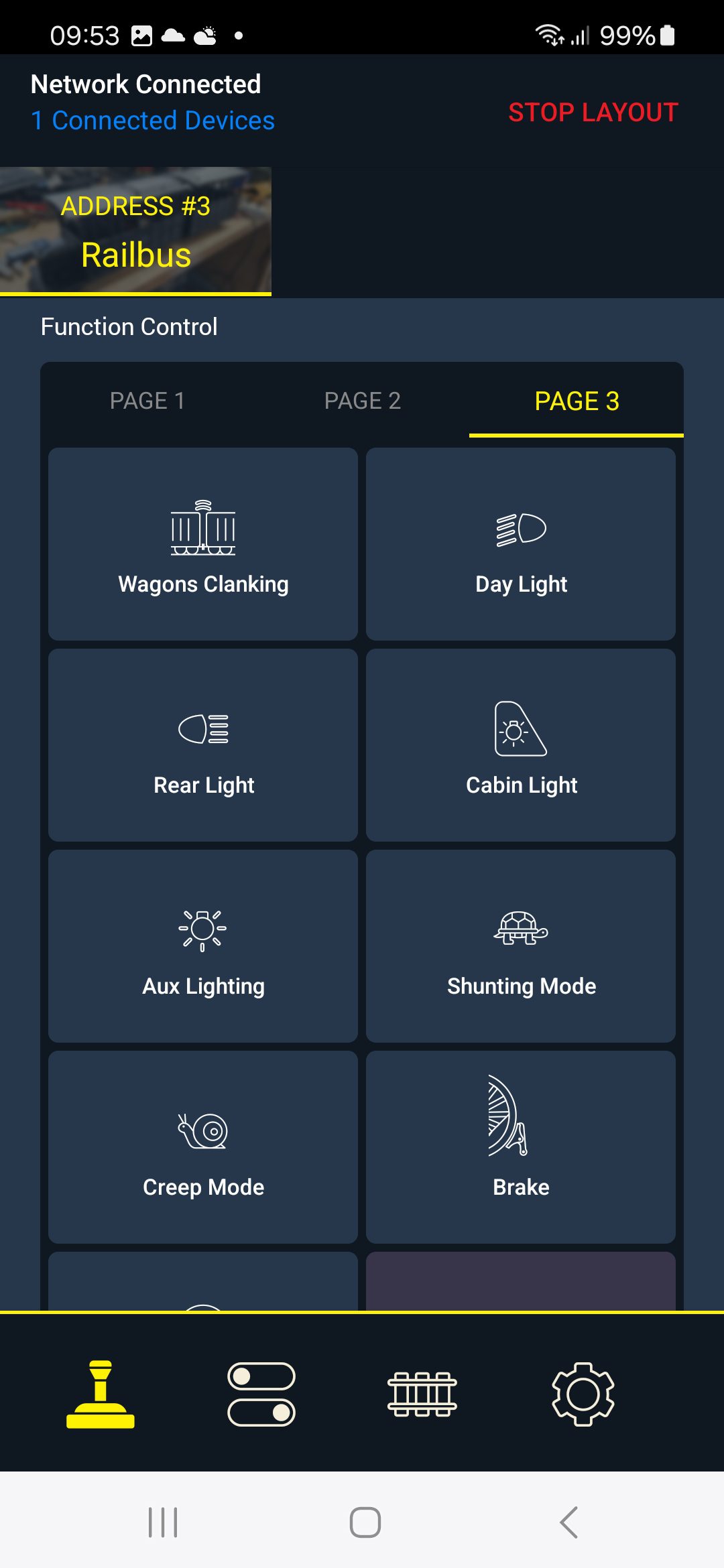
Sound effects page 3 (another 10 sounds)
Locomotive Settings Page 1
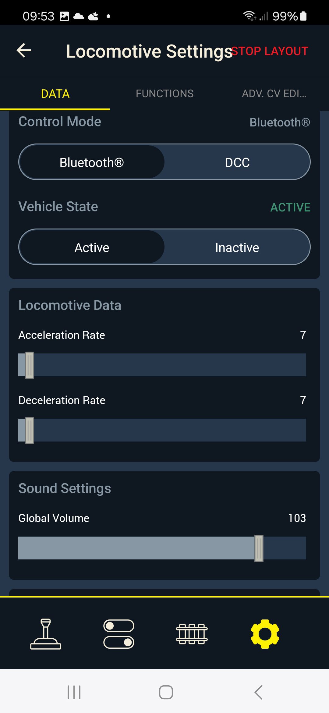
You can also customise your Sound Effects pages, for instance to put all your favourites onto the first page.
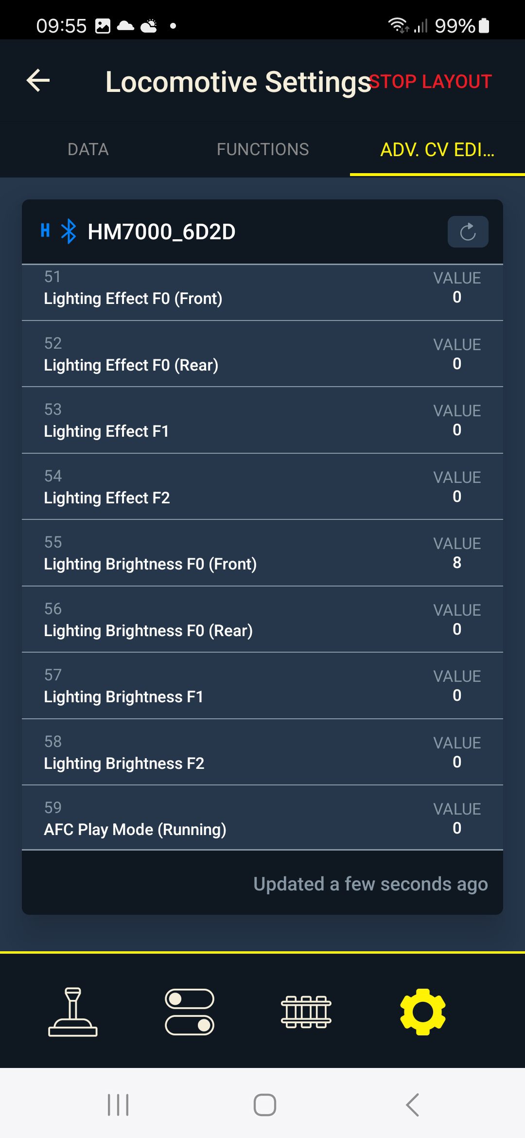
Many functions have their own parameters and you can set these to your preferences, e.g. brightness of lights, acceleration and deceleration curves. It can get quite complex!!
SO, WHAT ARE THE PROBLEMS?
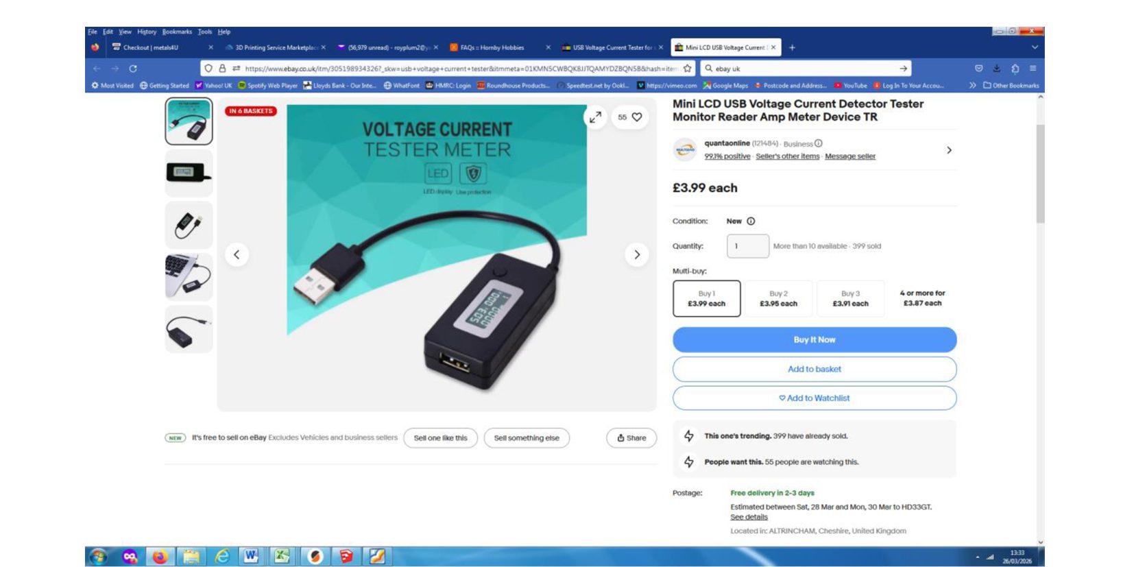
The only major issue I’ve found so far is that the HM7000 chip can only provide around 1000mA of power to the electric motor. This is 1 amp. For short bursts it can supply 1.5 amps. This should generally be enough for our locos, but if (like me) you have locos with 2 motors (say each powering its own bogie under a loco) you might easily go beyond what the DCC chip can handle and your loco will grind to a halt. You also get a warning in the App on your phone.
Motors can also draw a few amps if being used to haul a heavy train or climb a steep gradient…. particularly if you combine this with a tight curve. Put a current measuring meter (ammeter) between your battery and the feed to the loco and you can measure how many amps it’s drawing.
This little unit, available on e-bay for £3.99, will do the job nicely
There is a solution to this issue with additional circuitry allowing you to provide 3 amps of power. Our Gauge 1 colleagues have come up with this solution as they have the same problem, with the average Gauge 1 class 37 loco having 4 motors. This is a subject for a supplementary article.
In Conclusion
Yes, it’s a bit gimmicky… but it’s great fun!
It’s cheaper than almost any other system that offers wireless speed and direction control, lighting and sound.
The installation in the loco is very small.
It’s compact and very convenient. All you need is your phone… no bulky transmitter to carry around, and no more “Oh no… I’ve brought the wrong transmitter!”
Up to now I’ve had no range problems with the Bluetooth system.
Ideally your loco battery needs to be 12v DC or more.
I sometimes find the touchscreen operation on a small phone screen a bit awkward for my clumsy fingers and thumbs….. but luckily there’s a big red “Emergency Stop” button in the App which can be useful.
….. And have I mentioned it’s CHEAP for what you get!! The last time I bought one of the HM7000 21 pin chips it was £54, so watch out for special offers. This was in March 2026.
Go on… give it a try!
Roy Plum March 2026