
From Michael Bastow
First remove the cover from the normal spring housing and remove the spring.
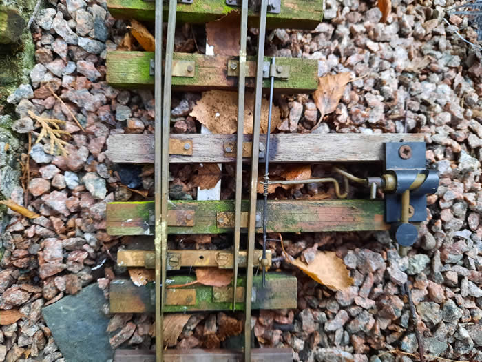
The new bias spring is 1.6mm brass rod which has a small piece of brass sheet soldered to one end and which is drilled to take a short pin which then locates in the central hole of the tie bar.
The other end of the rod is soldered to two brass screws as seen below.
This bias rod can easily be biased either way and also does the job of the original Peco spring in locating the tie bar.
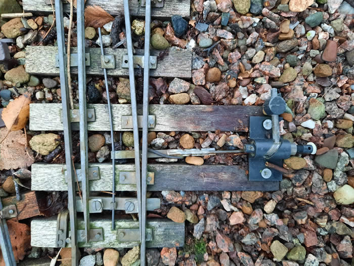
The next photo shows a point fitted with a replacement tie bar which is useful if you want to manually override the bias or control the point from a point lever.
The bias rod in this case is simply bent at a right angle at the tie bar end and inserted into the centre hole of the new tie bar, the other end is soldered as before.
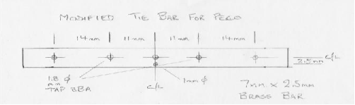
Fitting the new tie bar, drawing also included, involves carefully drilling off the heads of the rivets holding the Peco tie bar and removing this bar. Be careful not to damage the tabs on the rail!
The new bar is installed with two short 8BA countersunk screws through the remaining tabs into the tapped holes in the new tie bar.
New Tie Bar made from 7mm x 2.5mm brass bar. The 1mm dia hole allows the original Peco spring to be re-fitted if used as a normally operated point
From Gerv Wright :
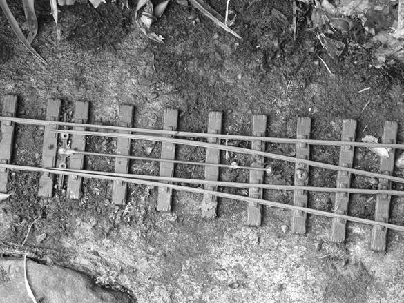
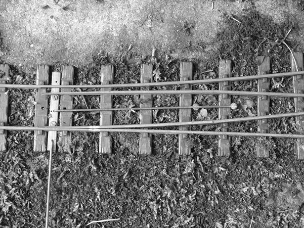
For the spring I use a length of carbon fibre obtained from Crossgates Model Centre [ See TRADERS for the a website ] This comes in various diameters. I used 1.2mm.
There is a fixed point at one end on a sleeper and the other end is attached to the tie bar between the point blades. For this connection, mine is a sliding fit using either a handrail knob or something similar I made. The middle of the spring is connected to the point switch.
In my setup the spring is weighted to the centre as I primarily wanted to prevent damage to the blades if an engine ran through the point with the blades set against the direction of travel. But this does enable the point to be sprung in either direction. If the object is to have it permanently sprung in one direction only, then the point switch could be replaced by another fixed point. (Sorry about using two different meanings for point!).
A certain amount of experimenting took place before deciding on the best length of spring.
If three link couplings are used it’s probably better not to put the spring between the running rails but to one side (as in the first photo) as a coupling left trailing on a coupling hook could get caught.