
Adventures in Ultrasonic Mist Maker Atomizing Foggers
(or water based steam effects)
Roy Plum develops a way of making steam effects for battery-powered locomotives
The technical stuff……
At some point a few years ago I decided to find out more (which was easy, as I knew nothing) about “Foggers”.
These are the things that many of you will know all about by now. They are used in ornamental dragons and such things to blow white “steam/smoke” from their nostrils, or in beauty treatment facials. In my case, I was OK for beauty treatments so it was the creation of “steam effects” that attracted me to the subject.
These “foggers” are available on e-bay for a small fee (when I last looked, £11.87 for 10) which seems quite reasonable to me. What you get is:
1. A small PC board (PCB) which would like 5v DC to operate it.
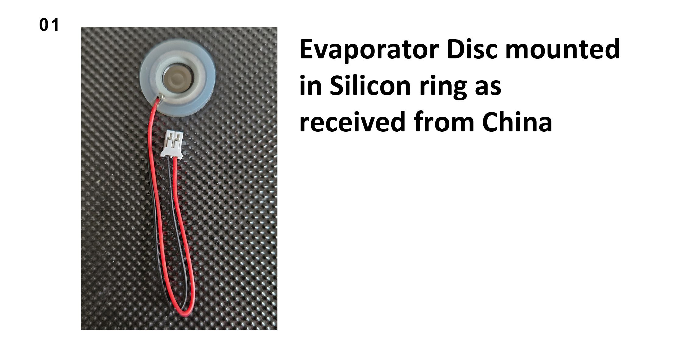
2. A shiny disc ultrasonic atomiser plate (or “Piezo Mister”) which plugs into the PC board via 2 short wires. This plate is mounted in an opaque silicone ring, diameter 20mm.
3. A length of “wick”.
4. Some bits of plastic designed to hold the wick against the atomiser plate.
If you’d like a “fogger”, search e-bay for Mist Maker Atomization Plate with 5V USB
Ok… for those of you who are technically minded, here’s the full description of the above:
Line board product voltage DV 5V
Current 300mA
Power 2W
Frequency 108KHz, fixed-frequency microcontroller
Driver board size: length 35 × width 20 × height 17mm (there will be a slight error)
Strong versatility, large amount of fog, stable performance, the chip has an automatic timer shutdown function (4 hours of continuous operation will automatically shut down to protect, if you need to reopen the power to re-press the boot can be).5V USB power supply mode, available MICRO charging cable power supply.
Atomiser Parameters
The net diameter of the steel piece of the atomiser is 16mm, the outer diameter of the silicone ring is 20mm, and the length of the wire is 8cm.
Product voltage DV 5V, current 300mA, power 2W, frequency 108KHz, number of holes 740, pore size 5um
The idea is that you place the 16mm diameter disc in the chimney of your building or electric steam outline loco and it delivers “steam” up the chimney. To do this it needs a water bath into which the wick is dipped (ooh, er matron) and the wick sits hard against the underside of the atomiser plate. Press the push button on the PCB (printed circuit board) and high frequency vibrations cause a jet of “steam” to emit from the atomiser disc. No heat is involved and the result is quite effective. Of course, it’s not steam at all but water vapour condensate at room temperature (I think!).
Press the button a second time and the jet of steam becomes intermittent on a cycle of approx. 5 seconds on and 5 seconds off. Pressing the button a third time switches the power off.
So far so good?? But my loco runs on 12v I hear you say…. Where do I get the 5v from for the atomiser?
Luckily, a search on e-bay for…..
Mini DC DC 3V-15V To 3.3/4.2/5V/9/12V Automatic Buck Boost Module Converter
…..will give you exactly what you need for £4.90 each. Last of the big spenders, eh?
(As a by the way, you can get all sorts of permutations of these “Buck” convertors, and they can convert voltages upwards as well as down!! They are very efficient too, so your batteries won’t be drained any faster than normal).
Before we leave the technical specs for all this gear, you might be interested to know more about these atomiser plates, the sizes available and their water consumption rates. Here’s the website of one of the manufacturers which tells you all this and much, much more….
Mesh Base Atomizers
I’ve never dealt with these people direct. All my purchases are from e-bay, but it’s interesting to see the variety of sizes available.
Of course…. The big bonus of these atomiser systems is that they are cheap to buy and very cheap to run, just needing water! No fancy smoke fluids required, and the atomiser won’t burn out if left running without liquid.
And now, the practical stuff…..
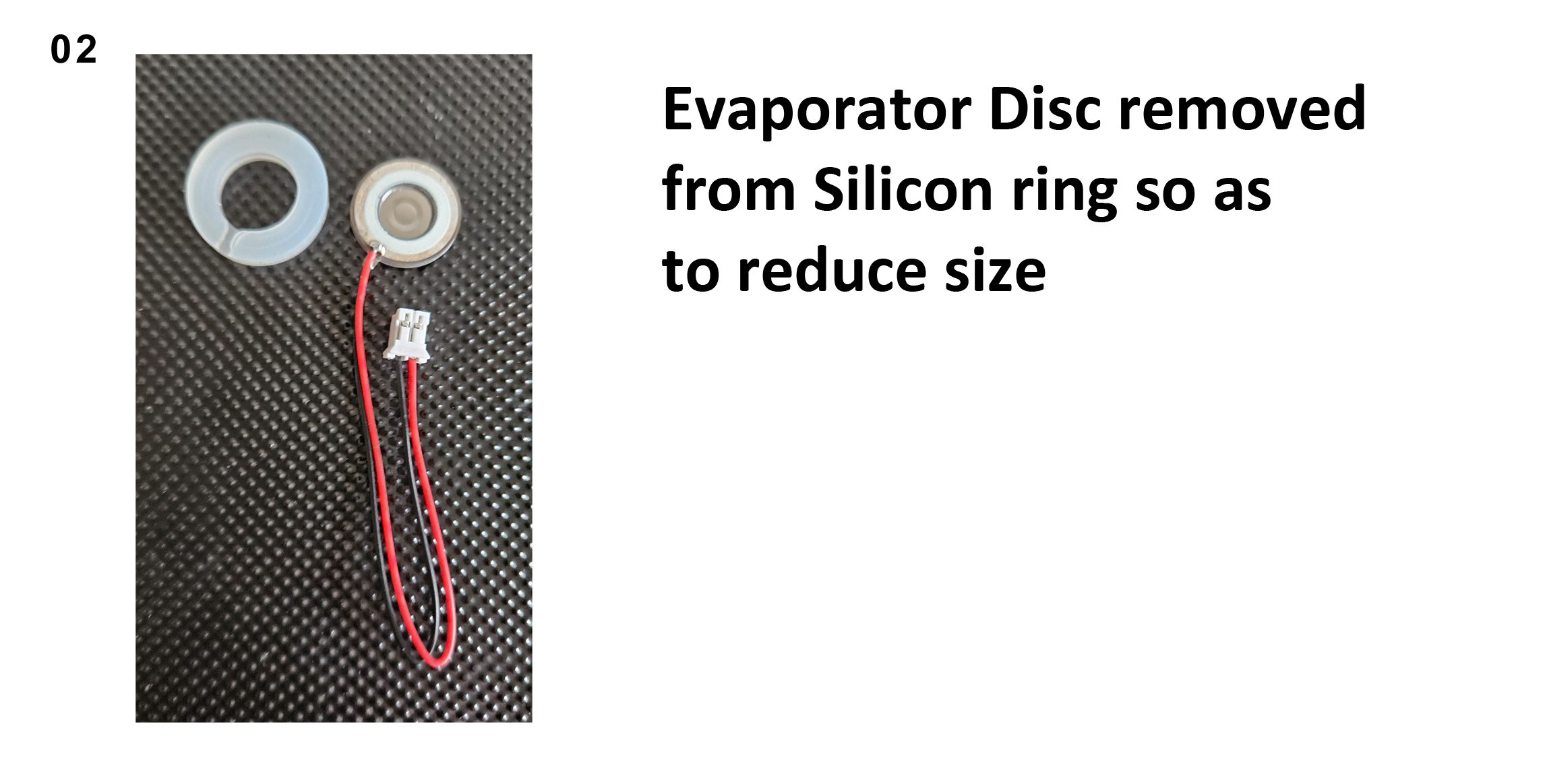
The biggest problem I’ve found in using these things is the diameter of the atomiser disc and the diameter of the wick. For insertion into a model steam loco chimney we need a small diameter disc and wick.
I ordered some spare wicks from e-bay and fortunately these turned out to be of narrower diameter than those supplied in the complete kits. A standard wick is approx. 10mm diameter, whereas the “spares” turned out to be 7.5mm in diameter… much better for our purposes.
The atomiser discs as delivered sit in a silicone ring of 20mm diameter.
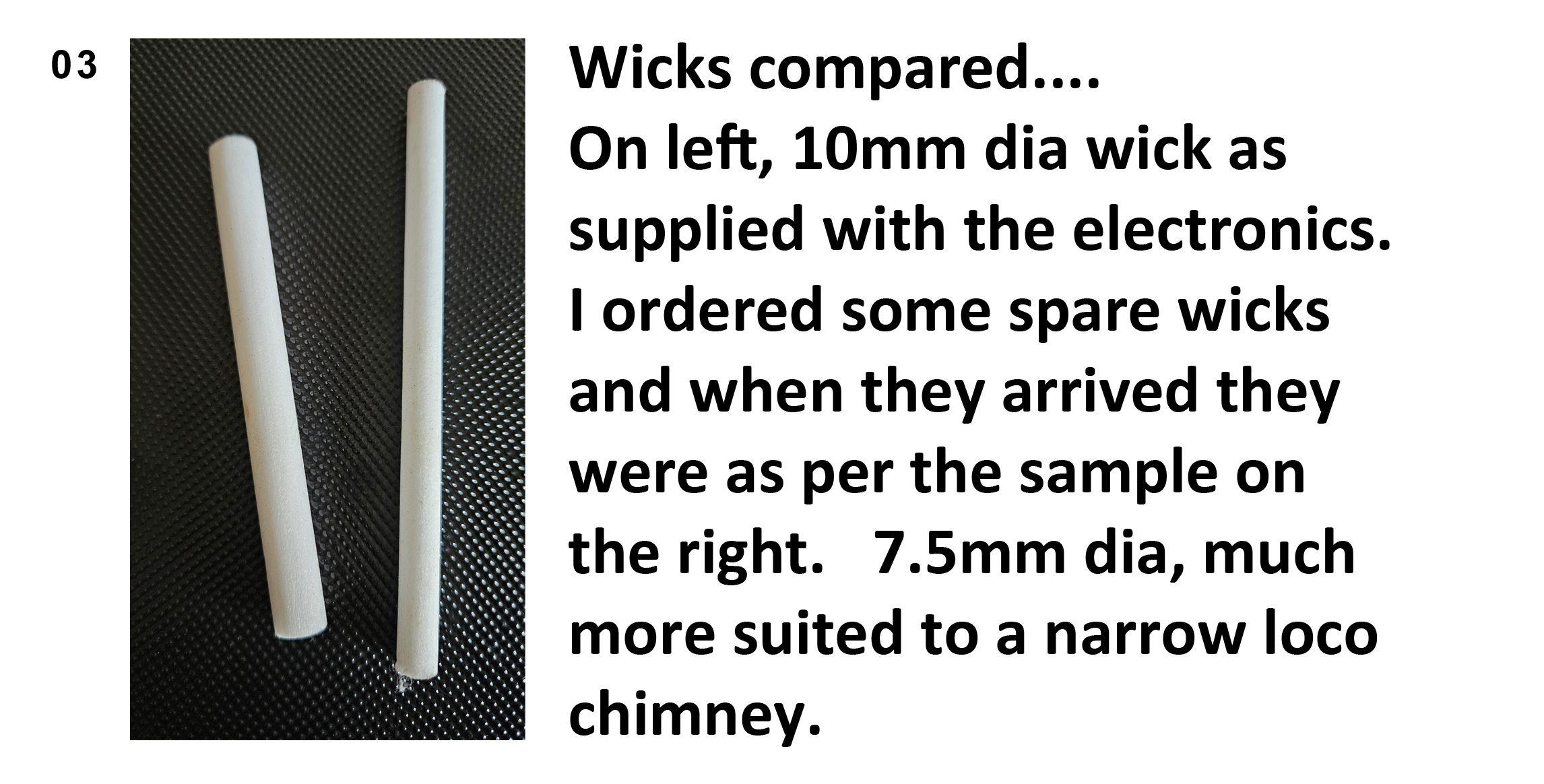
I carefully removed the atomiser from the ring to make the system smaller. This doesn’t seem to affect its performance.
Initially I placed the atomiser disc (which I’ll call the “smoker” from now on, as I’m sick of typing the full name) at the top of the chimney so as to get the full steam blast effect. If the chimney is the “balloon stack” type (spark arresting) this is a real bonus as the fat chimney easily holds the smoker disc and can also be used as the water tank.
I 3d printed my own disc holder and water tank and found this a convenient way of installing the smoker systems. When the chimney bore was under 16mm, the smoker disc had to sit inside the top of the smokebox directly under the chimney. This initially resulted in poor steam output until I spotted how Andrew Wilkinson at Huddersfield Railway Modellers had installed a system in their blacksmith’s shop. By leaving an air gap over the disc, this allowed the steam “jet” to entrain air and the jet would then rise several centimetres up the chimney and still look good. The properties of gasses in jets would seem to be the same with atomisers as it is with the burner jets in our steam locos; the right mix of gas and air is required to get a roaring flame and the same “correct mix” is needed for our vaporiser “steam” jet to reach the top of a narrow chimney. I think it’s something to do with the venturi effect (or it might not be!).
So far so good, but there was still the issue of having to switch the system on by pressing the button on the PC Board. Initially I was poking wire rod through an appropriately positioned hole to effect the switching, but then Nick Midgley told me you could solder a wire across the switch terminals to short the switch out, and the system still worked perfectly well.
So now I could turn the steam effect on and off by controlling the 12v feed going to the Buck convertor, which in turn sent 5v to the smoker.
And now, the real meat of this article……
After a few minutes of initial admiration of the “steam” effects, a voice at the back was heard to say “it’s a shame it doesn’t chuff”. Some people are never satisfied.
I left the subject for a year or more and was quite happy watching my electric locos “chug” around with a constant plume of steam at the chimney. Then I spotted that Hornby had announced a range of locos with water based steam effects that “chuffed” in synchronisation with the wheel rotation and the prototypical number of cylinders… i.e. 4 chuffs per wheel rotation for 2 cylinder locos and 6 chuffs for 3 cylinder types, etc. I really wanted to know how this magic was achieved! I just assumed it was electronic wizardry associated with DCC control. Incidentally, Hornby call their range “Steam Generator Models”.
There are several review/demos of the system on You Tube. Here’s one if you’re interested:
Anyway, back to 16mm scale now. Nick Midgely achieved some good results with an electro-mechanical system based on split rings wrapped around the loco axle and “wipers” to collect the current as the axle rotated. I knew that this was well beyond my engineering bodging skillset. I needed something small, reliable and preferably simple.
Time went by and the challenge was left fallow. Then as part of another project, I was looking for some kind of optical switch system to control the position of a sector plate (don’t ask!). Once again, e-bay to the rescue and I came across this…..
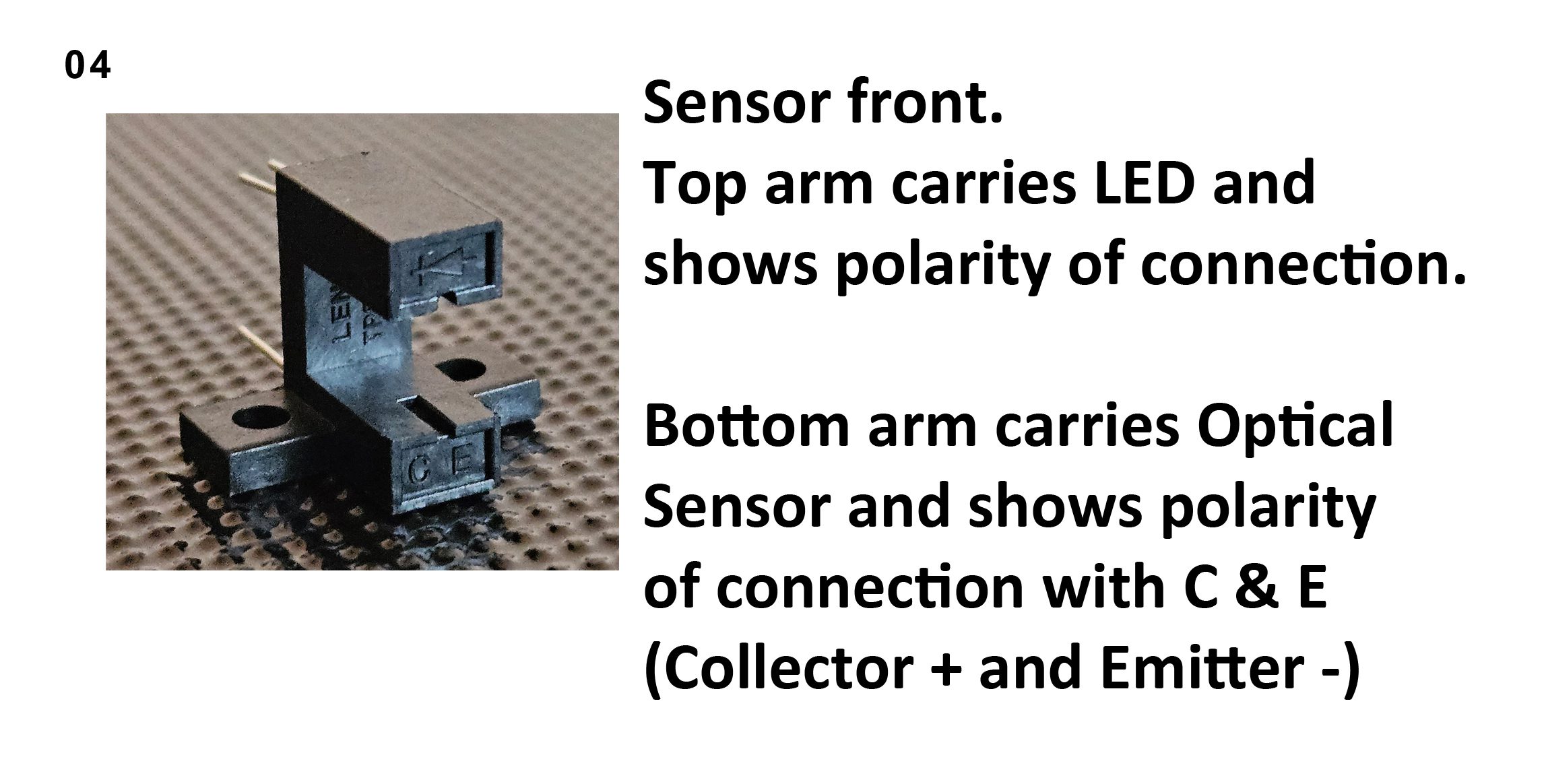
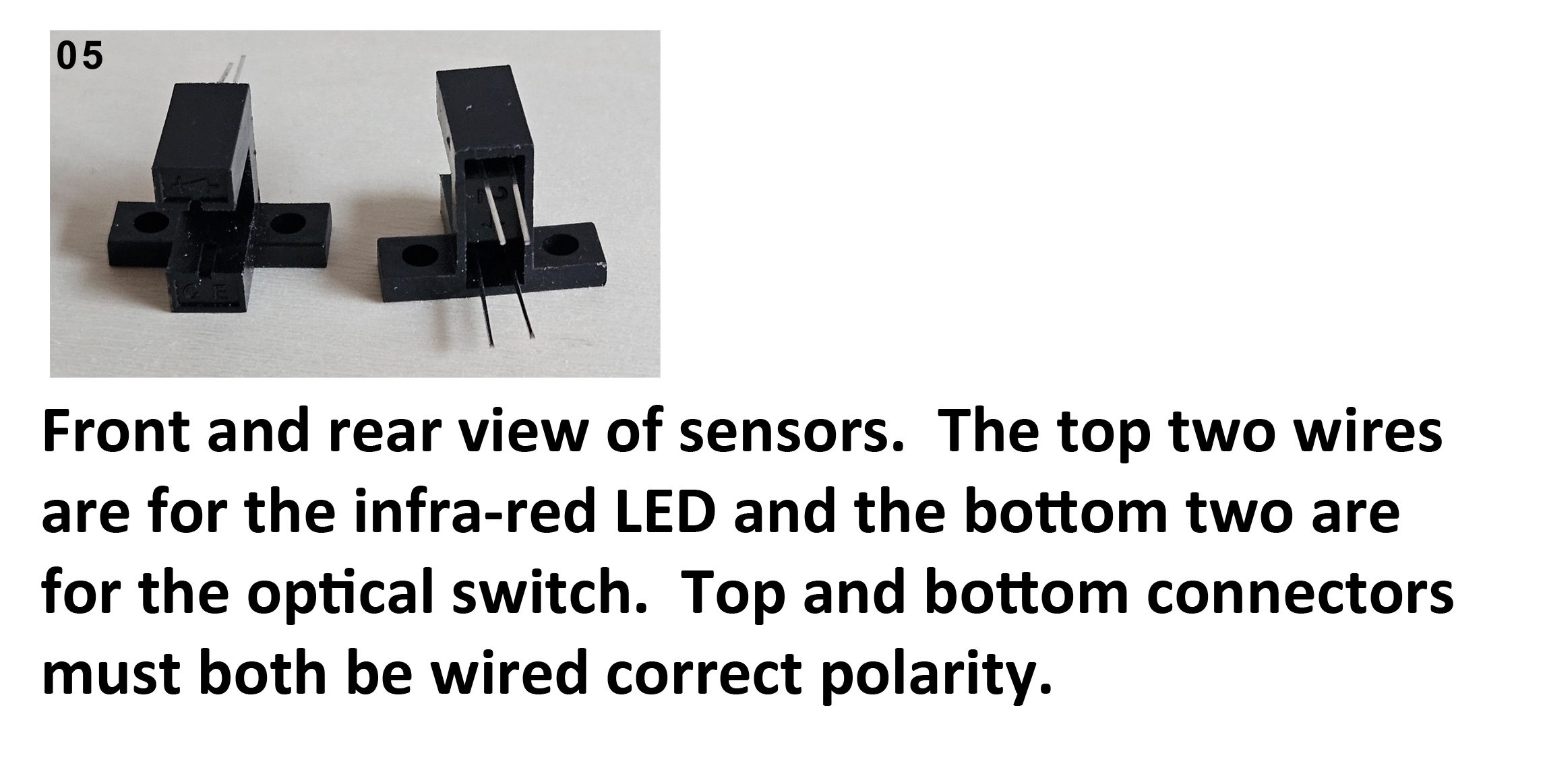
Slot Optical Switch Photoelectric Sensor Opto Interrupter Transmissive Infrared
10 for £2.46 plus £2.39 delivery from China.
I went for the type referenced ITR20005-Fas it had built in mounting holes.
(Are you detecting a pattern in my retail preferences here?)
Evidently, these units are often found in computer printers and photocopiers where they count the pages being produced. There is an infra-red LED in one arm of the unit and a photo receiver in the other, the whole arrangement forming a U shape. As an item passes through the “U” it breaks the beam from the LED and the photo receiver changes its state as it moves from the light to the dark. When the light shines on the receiver, it passes a current of 20mA. When it stops seeing the light, it passes 0mA…. so it’s a type of on/off switch. 20mA is 20/1000 of an amp or 0.02 amps i.e. not much as all!
Luckily, the unit likes a supply or 5v DC…. And that’s just what we’re using for our smoker!
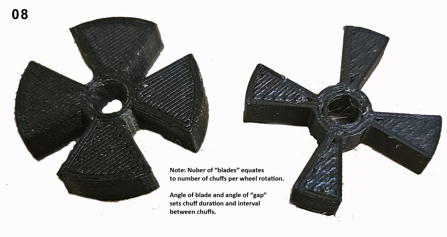
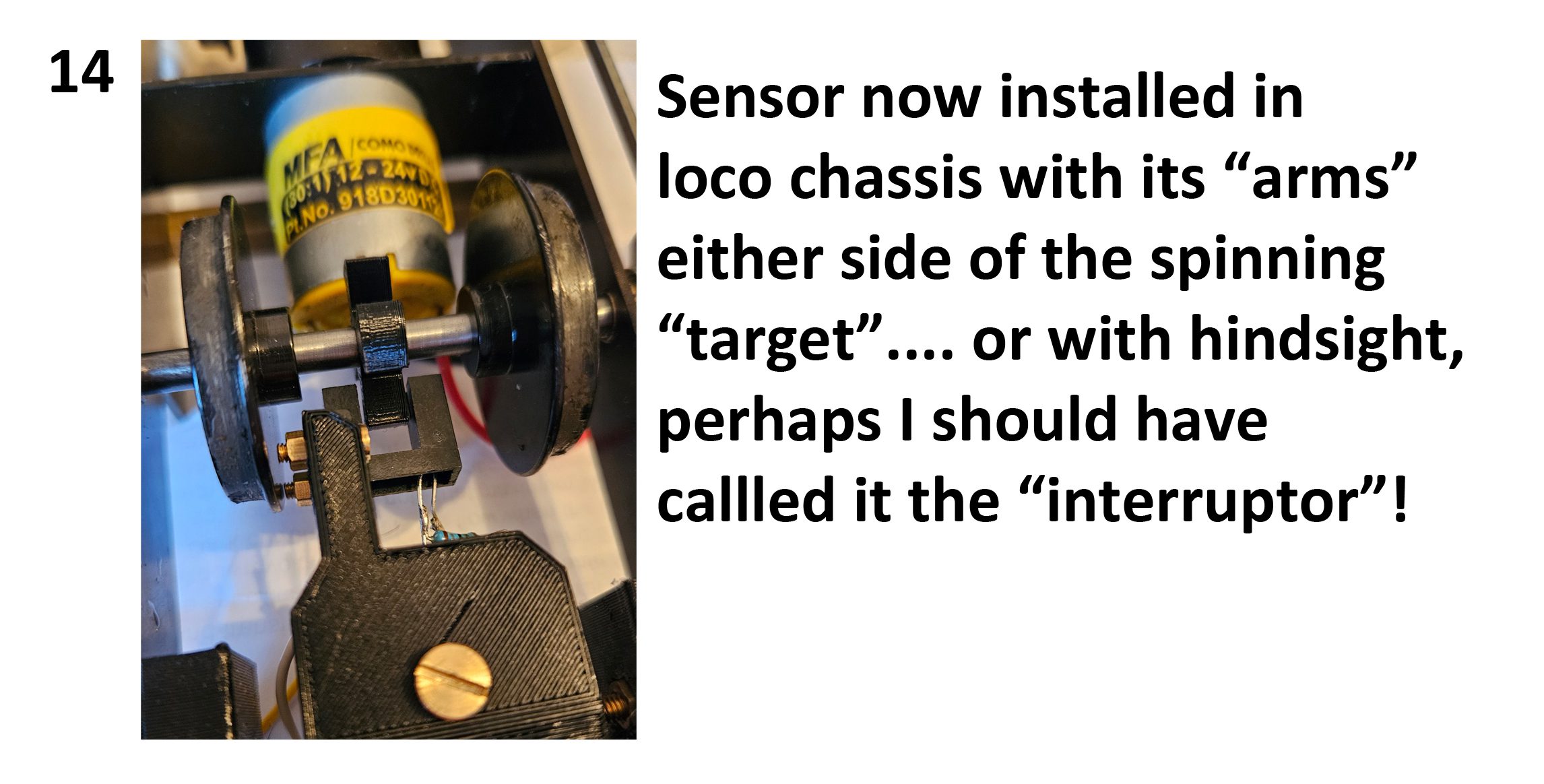
So, in theory, we can mount a 4 bladed “fan” or “maltese cross” arrangement (which I’m now going to call the “target”, but thinking about it, it really is an “interruptor”) onto our loco axle and mount the whole thing so that the target breaks the light beam 4 times per wheel revolution… and we can use this to start and stop our smoker so that we get 4 chuffs per wheel revolution. My experimental “targets” are shown below…
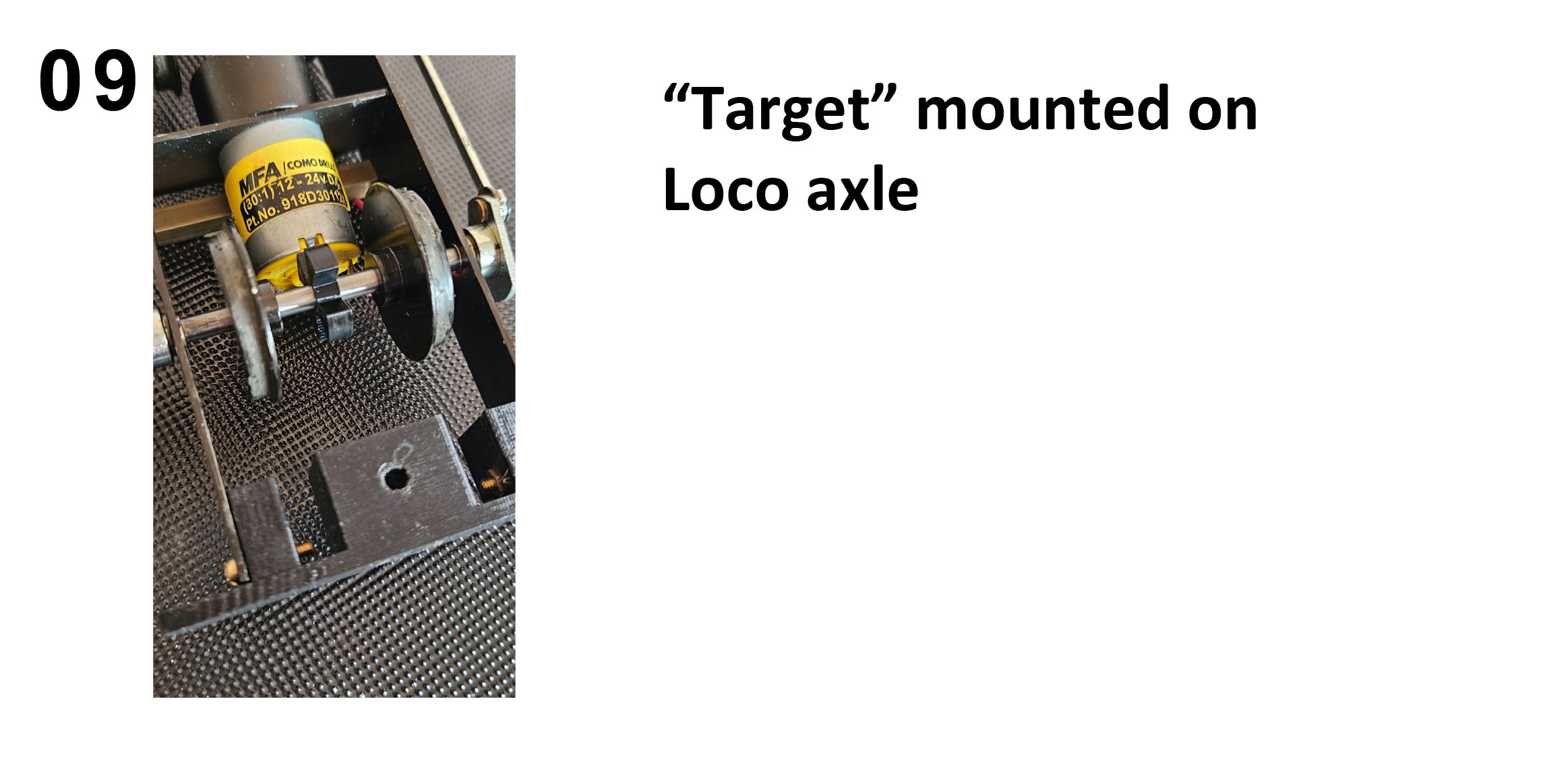
The target mounted on the loco axle is shown below…
Just one snag. The maximum current our detector can pass is 20mA. The smoker needs 300mA, so we haven’t enough current to make our smoker operate. By gad, isn’t life disappointing?!
When I hit snags like this I find there’s only one thing to do…. ask everyone I meet if they can think of an answer. I mentioned that I haven’t a clue about electronics, so when I got the answer “you need a transistor” I wasn’t much the wiser. When I was doing “O” levels we were still studying the thermionic diode, even though we’d all had tranny radios for several years!
Next came a bit of learning about transistors. I can recommend YouTube for such things. For the benefit of myself and other clueless individuals, I found that a transistor works by being fed a small current of electricity as a reference and allowing a large current to pass proportionally. Simples, eh?
E-bay sent me some transistors
To bring the technology down to my level let me use an analogy. Imagine that you are standing at the top of Niagara Falls with a hosepipe in your hand. Magically, if you turn the hosepipe off, the Falls stop too! If you turn the hosepipe on to a trickle, the Falls start trickling… and if you turn the hosepipe full on, the Falls go into full spate!! That’s essentially what a transistor does. It has three “connections” or “legs”…. One for Niagara Falls in, one for Niagara Falls out, and the other one is for your hosepipe.
(My physics teachers must now be spinning in their graves).
Get the idea?
Next challenge… what sort of transistor to use, as they come in all sorts of shapes and sizes? I decided on a big one! I’m sure it’s overkill, but in practice I found it works. For future projects I’m going to try the smaller transistor so I can save space. (Breaking news… I have tried it. I found that the results weren’t as good).
I went for the ECSiNG TIP3055 NPN Transistors for Electronics Professionals Enthusiasts General Amplifiers Low-Speed Switches TIP3055 NPN In-Line Transistors TO-247
These were £11.39 for 10 on Amazon.
(See, I don’t use e-bay all the time).
I won’t draw the circuit for my first attempt (because it didn’t work). What I did was use the output from the optical sensor (5v 20mA) to drive a larger current (5v 300mA) via the transistor to feed the smoker PCB. The idea was, whenever the light shone onto the sensor the smoker would make steam. When the light was cut off, the smoker would stop. This worked fine at crawling speeds, with individual chuffs looking great. Unfortunately, as the loco sped up, the smoke stopped altogether.
I made a small test rig where I could rotate an axle by finger and thumb and see the result. Here’s a short video of it in action:
And here’s what happened when I tried it in a loco:
Disaster!! No smoke when the loco went faster. This was because as the target spun faster and faster, it cut down the light hitting the sensor until there wasn’t enough to make it pass a current and hence, no smoke was produced. How really annoying.
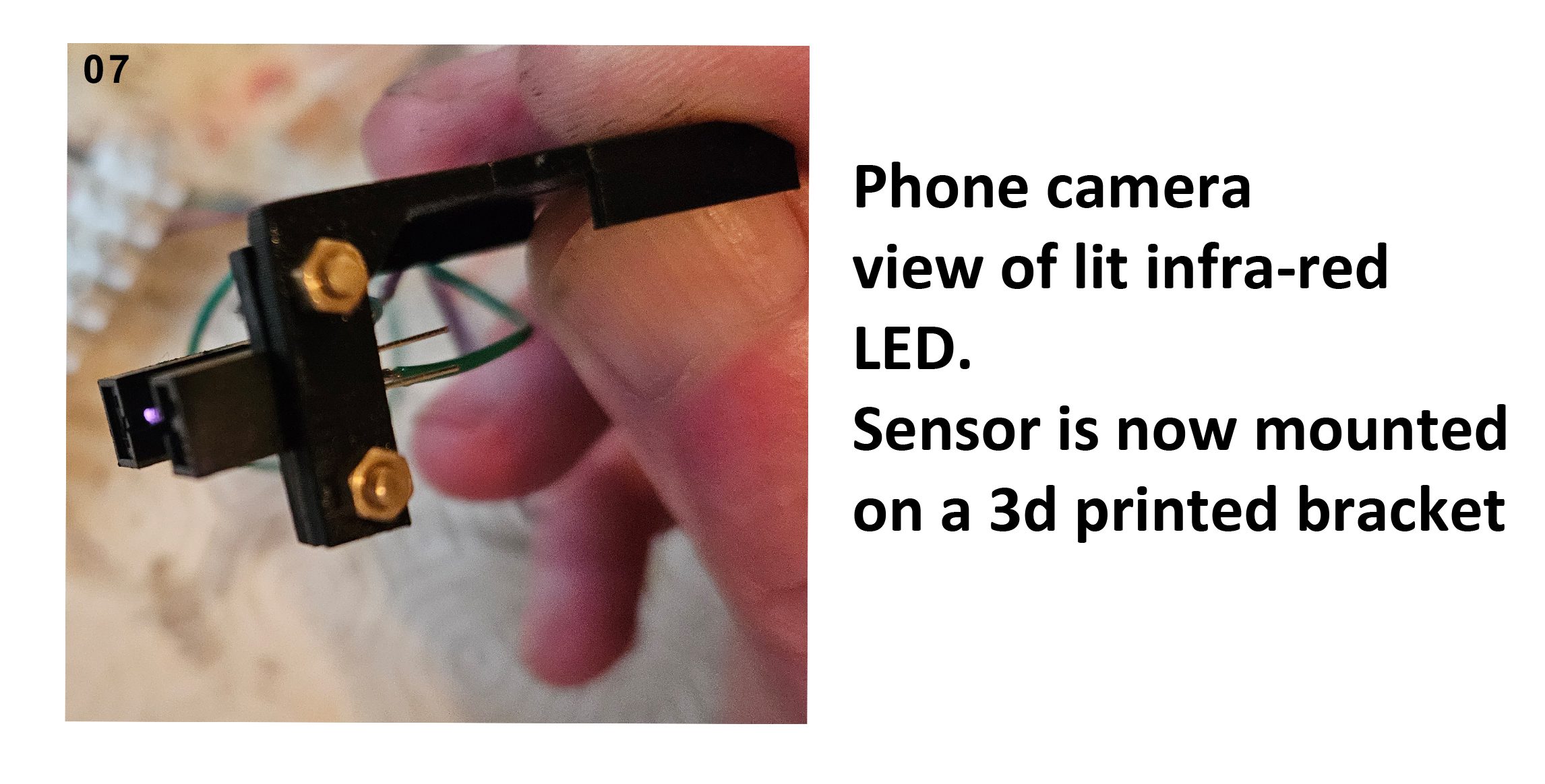
At this point, I can also throw another spanner in the works. Just looking at the infra-red LED in the optical sensor, you can’t tell if it’s working or not. The human eye can’t see infra-red light! There is a solution to this…. Point your phone camera at the LED and you’ll see it glowing on your phone screen. Video chips can see infra-red light. I just mention that as a useful by-the-way.
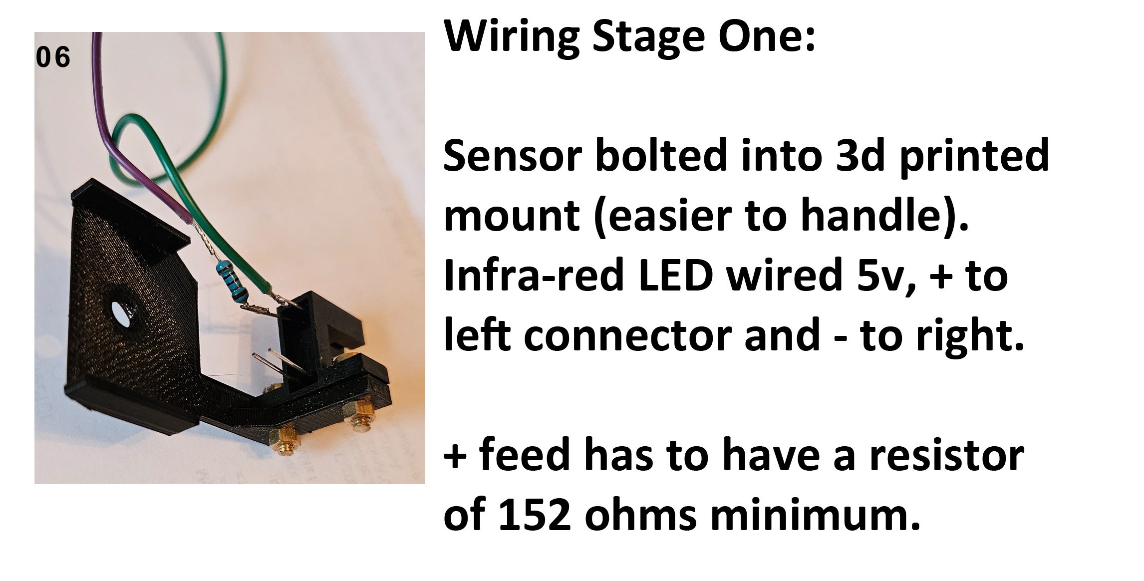
The initial wiring of the Infra-Red LED is shown below…
Using the phone camera to test that the LED is working is shown below…
Back to the smoke problem with the loco moving at anything faster than a crawl……
I decided that what I needed was a system that turned the smoke OFF when the light hit the sensor and turned it back on when there was no light. Time for the thinking cap, because a transistor can only turn electric on when its gets a current from the optical sensor. I needed the electric to be on for the smoker when the current from the optical sensor was switched OFF…. which is the opposite to the way my transistor was currently working (get the pun?).
Those of you who enjoy watching “Only Connect” will see that the answer is simple, but I had to “phone a friend” again.
The solution was to have the smoker “making smoke” as its normal condition, and to use the transistor to by-pass (or short out) the smoker when the light beam shines on the receiver. So dark = make smoke, light = stop smoke.
Now when the loco gets up speed, the light on the sensor drops to near darkness and the smoker keeps making smoke continually. When the loco moves slowly, the sensor has time to “see the light” (4 times per wheel revolution) and stops making smoke, so we get the intermittent chuffs that we want.
Here’s the video of the test:
The circuit design is shown below
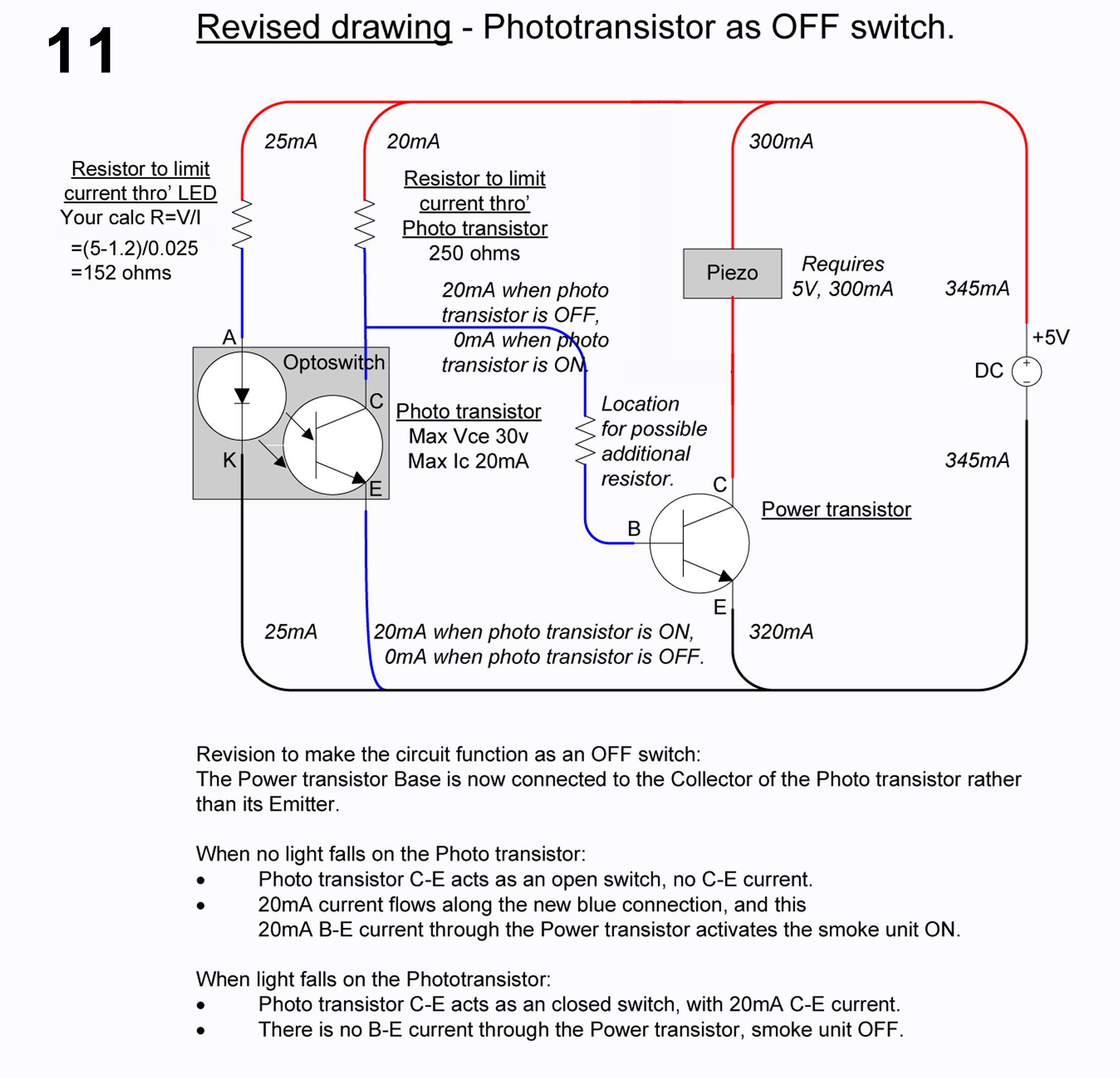
The diagram refers to a “possible additional resistor”, and this turned out to be 1.5k ohms when using the large TIP3055 transistor.
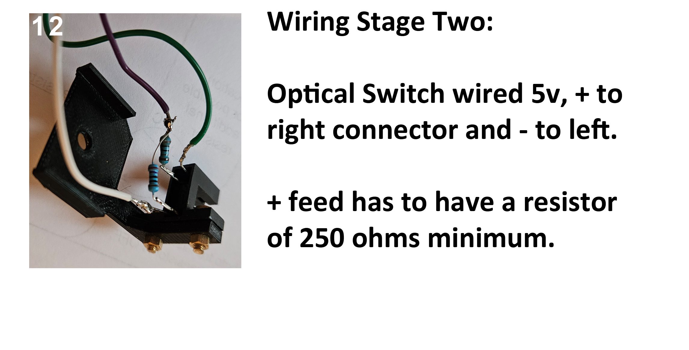
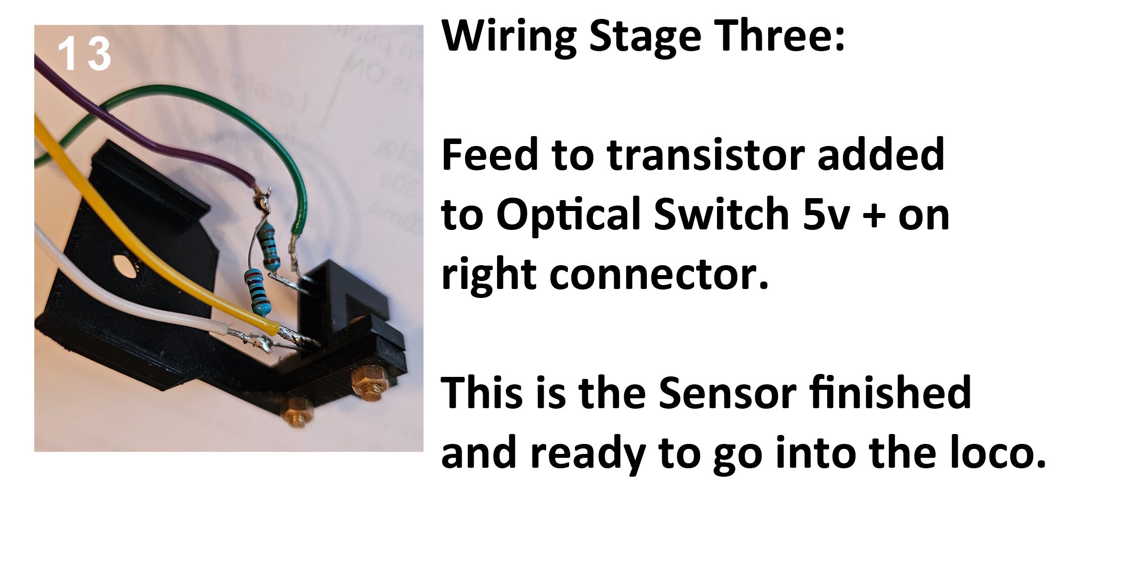
The final stages in wiring the sensor are shown in photos below…
The complete installation of the sensor system in the loco is shown below…
And the proof of the pudding…..
Here’s a video of my steam tram showing its chuffing best exhaust effects…….
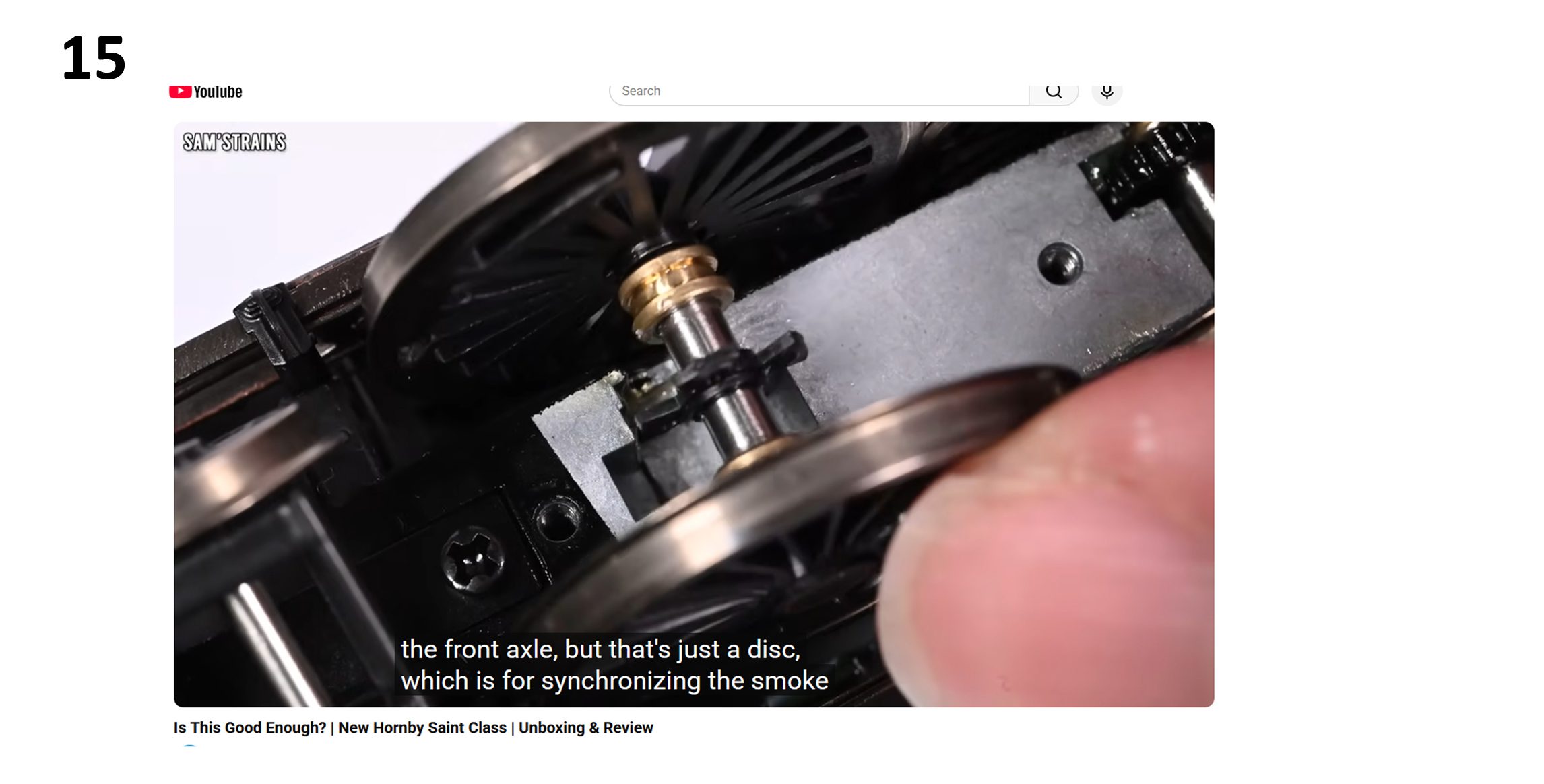
And how do I think Hornby do it? There’s a clue in a still that I grabbed from a “Sam’s Trains” video when he dismantled Hornby’s new “Lady Of Legend” loco
Postscript: Anyone who knows a bit about electronics will have realised by now that I’ve done this project largely by experimentation and guesswork. If anyone knows of a better or simpler way of achieving the end result I desire, please get in touch and tell me!!
February 2026