
A joint Project researched by Alan Poxon with Design, Print and Build by Roy Plum
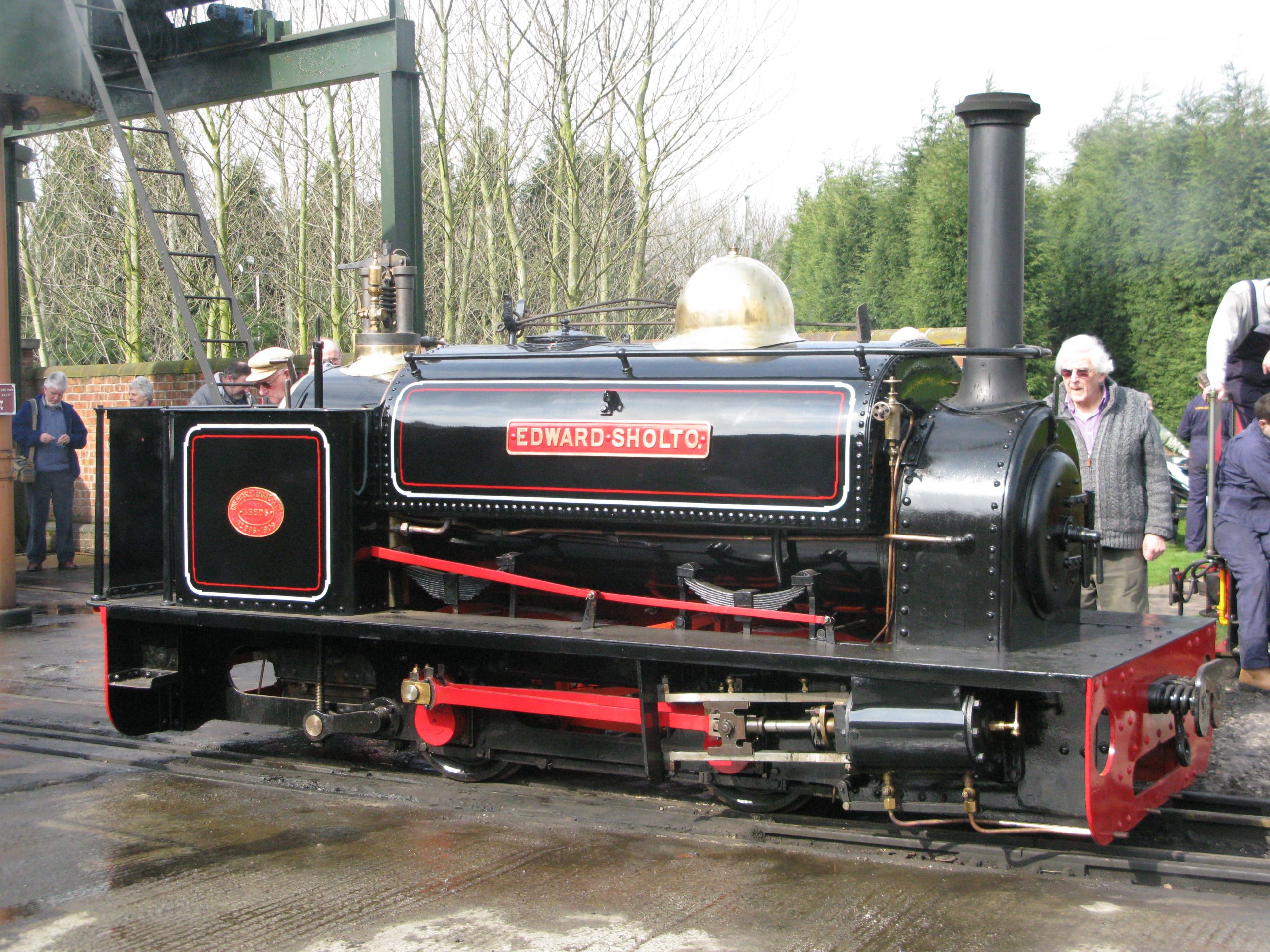
Edward Sholto is a well known Penrhyn Quarry Hunslet. It was the last of the Hunslet Large Quarry Class to be built and was, in 1909, the last new locomotive purchased by Penrhyn Quarry. This 0-4-0 saddle tank locomotive was named after Edward Sholto Douglas-Pennant, who became Lord Penrhyn in 1907 and inherited the Penrhyn Quarry. The locomotive was withdrawn from service in 1956 and, after being sold, it was exported to Canada in 1961. Edward Sholto passed through several owners in the USA before being repatriated in 2006 and subsequently restored to steam in 2009. The locomotive currently resides at the Beamish Museum.
First appearance of Edward Sholto after rebuild
March 2008 Statfold Barn.
Photo: Andy Cooper
This locomotive was, however, not the first to carry the name Edward Sholto. Penrhyn Quarry purchased a total of sixteen Hunslet locomotives, starting with Charles in 1882 and ending with the aforementioned second Edward Sholto in 1909. Prior to this, Penrhyn acquired motive power from other manufacturers, starting when steam traction was first adopted in 1875. The first of these locomotives was built by Hughes of Loughborough. This engine was a short wheelbase 0-4-0 well tank with an open cab and tall chimney. The locomotive was named George Sholto, father of Edward Sholto, but had limited success.
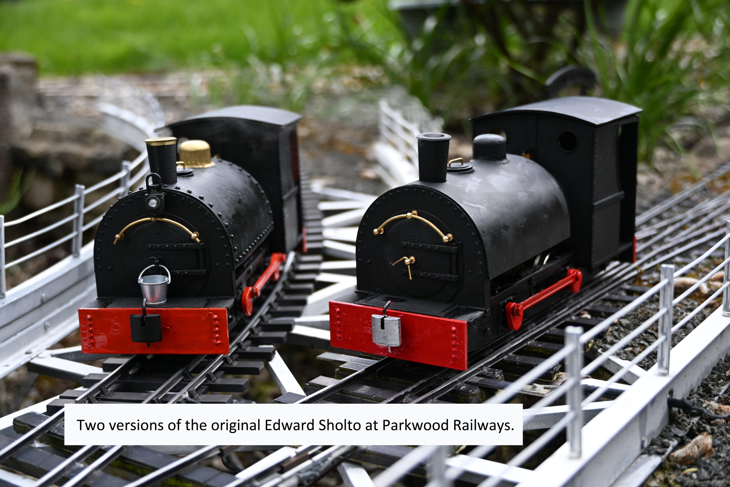
The next locomotive was purchased in 1876 and was the first to carry the name Edward Sholto. This was a 0-4-0 saddle tank from deWinton of Caernarfon, who went on to supply Penrhyn Quarry with two further side tank locomotives and six of the better known vertical-boilered engines. This original Edward Sholto had a 5 foot wheelbase with 24 inch diameter wheels, sharing these, and other dimensions, with the Large England locomotives which had already proved a success on the Ffestiniog Railway. However, the Penrhyn engine had an enclosed cab and a slightly shorter overall length of 14 feet 6 inches.
Most of the dimensions for Edward Sholto have been gleaned from surviving correspondence prior to the delivery of the locomotive. Further details are sparse in the Penrhyn Quarry records compared to other locomotives in the fleet. There are two photographs taken in the quarry that have Edward Sholto in the background. One blurry image has a front view of the locomotive that shows a smokebox door with a curved handrail above. A second photograph shows only the front end of the locomotive peeping out from behind equipment in the quarry, but it confirms the smokebox details and has allowed the height of the funnel top to be determined as 7 foot 6 inches above the rails.
Edward Sholto was only the fourth locomotive ever built by deWinton and had cylinders inside the frames with the frames outside of the wheels. Two injectors and powerful brakes were specified on the original order from Penrhyn. The locomotive was supplied with solid cast wheels but these were replaced with steel tyres in 1878. In the same year, new tubes were fitted to the boiler after only sixteen months of service. A surviving piece of evidence, dating from May 1900, is a hand drawn, annotated sketch of the dimensions required for a replacement saddle tank for Edward Sholto that was fabricated by Hunslet rather than deWinton.
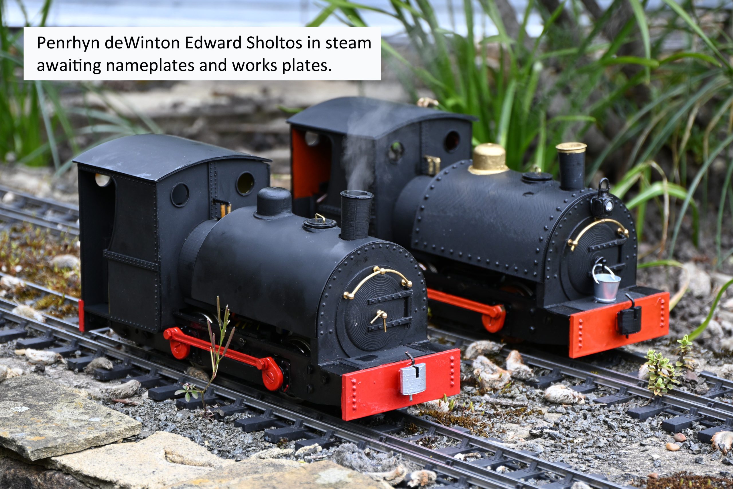
Edward Sholto is believed to have run with an unlined black livery with red buffer beams. The power of the locomotive proved to be below expectations. However, deWinton went on to supply two 0-4-0 tank engines that were effectively narrow gauge copies of standard gauge locomotives. The first of these was Hilda, built in 1878, followed by Violet in 1879. The original Edward Sholto ceased to work the mainline from the quarry to Port Penrhyn in 1882 when Charles was supplied by Hunslet. However, the original Edward Sholto continued to work within the quarry, on lighter duties, until it was scrapped in 1907, after a total of 31 years service.
Further Reading
DeWinton of Caernarton: Engineers of Excellence by A. Fisher, D. Fisher & Dr G. Pierce Jones.
RCL Publications, 2011.
Design, Print & Build Edward Sholto in 16mm – by Roy Plum
“Did I fancy printing another loco?” was the question, as a few sheets of badly photocopied A4 were thrust into my hand.
“It’s a horizontal boilered de Winton, one of only three they ever made. It ran on the Penrhyn Railway”.
Always up for a challenge and something to do while my wife watches endless football and cricket on the telly, I examined the paperwork.
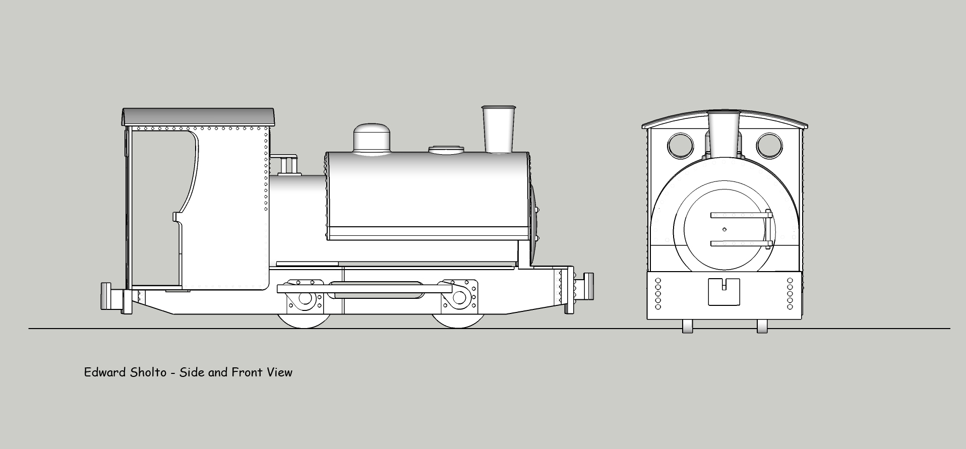
A couple of things jumped out immediately. The information was sketchy to say the least and this would give me a lot of freedom to imagine whatever detail I might like to add. All I had to go on were a few key dimensions, a side and front elevation drawing (based on a photograph), and a sketch of the saddletank made by Hunslet when they supplied a replacement tank in 1900.
I immediately saw some potential for an interesting project. Although the prototype was steam driven, the plan was for the 16mm loco to be electrically powered.
The saddletank was quite large and extended from the smokebox front to over halfway along the loco. This would be great for hiding all the electronic “gubbins”, and might even be big enough to hide an electronic water vapouriser which would sit under the chimney.
There was no visible valve gear. Indeed, there were no visible pistons! The only visible details on the frames were the axleboxes and a coupling rod between the cranks on the two axles. This meant that one axle could be free from delrin chain and cogs, so it could be easily fitted with an optical “interruptor” to trigger the steam “chuffs” as the loco progressed along the track.
Having accepted the challenge, I sat down to look at the dimensions of the loco in 16mm scale.
The wheelbase was a known dimension (5 feet in the real world, 80mm in 16mm scale) and everything else was scaled from that by laying ruler over the drawings of the front and side elevations.
The first task was to draw the loco in 3d on the computer. Being self-taught I wouldn’t claim to be particularly good at this. In fact, I’m still using “Sketchup” which really is a raw beginner’s 3d drawing package…. So much so that the reviews of such software usually dismiss it as a total non-starter. I don’t care!
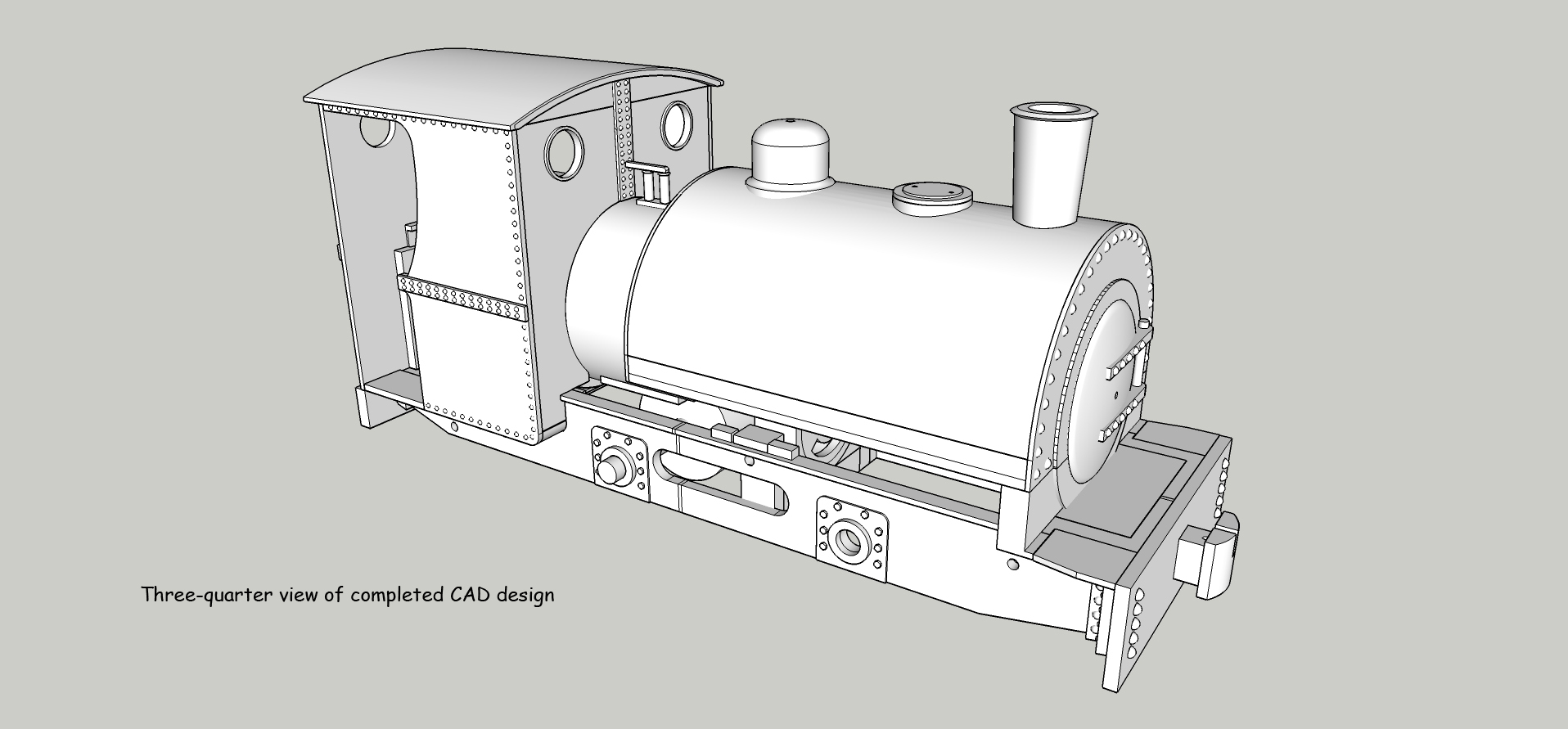
The loco was a very simple design but one or two details were of concern. The cab was supported on the thinnest of frames, and the cab back was a thin sheet of material seemingly magically attached to the cab roof and cab floor by nothing more than prayer. The rear buffer beam was very shallow too… in fact the whole back end looked a potential disaster. I was left wondering what on earth the de Winton designers had been thinking.
Having drawn the loco, the next stage was to decide how to break it down (or “explode” it) into printable parts.
At the same time, I was thinking about the battery pack. I’m a big fan of LiPo cells, giving lots of running time for a small pack size… and 11.1volts from a three cell pack to boot! A 2200mAh pack looked like it would fit in the boiler space so I started to design from that premise.
In my designs, I like to keep the following objectives in mind:
- As much as possible should bolt together rather than be glued. Often my initial ideas turn out to be non-starters, or better solutions come to mind as the build progresses. Being able to easily break the model down by un-bolting sections means that I can upgrade/ redesign / adjust parts as I go along without having to throw the whole model away and start everything afresh.
- The model should have a long running time on a single battery charge.
- The LiPo battery should be easily removed from the model for charging. (Charging inside the model is a non-starter on safety grounds).
- Steam outline locos should chuff water vapour if at all possible.
- The water storage tank for the vapouriser should be easily filled and emptied.
- All parts should locate into slots or corners, so that they “register” into position and line themselves up. The objective is to avoid having to measure to identify correct positioning.
- All nuts should be held captive in the design to make assembly easier.
- The model should be easy to assemble (and disassemble for maintenance and upgrade).
- The finished model should be robust enough for normal garden use. No shelf queens!
- Having sound effects would be very desirable.
The next stage was to explode the drawing into component parts….
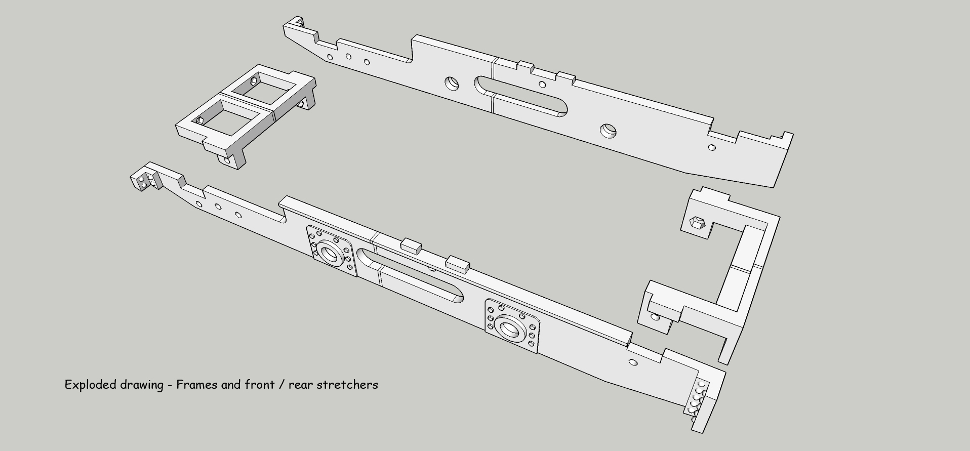
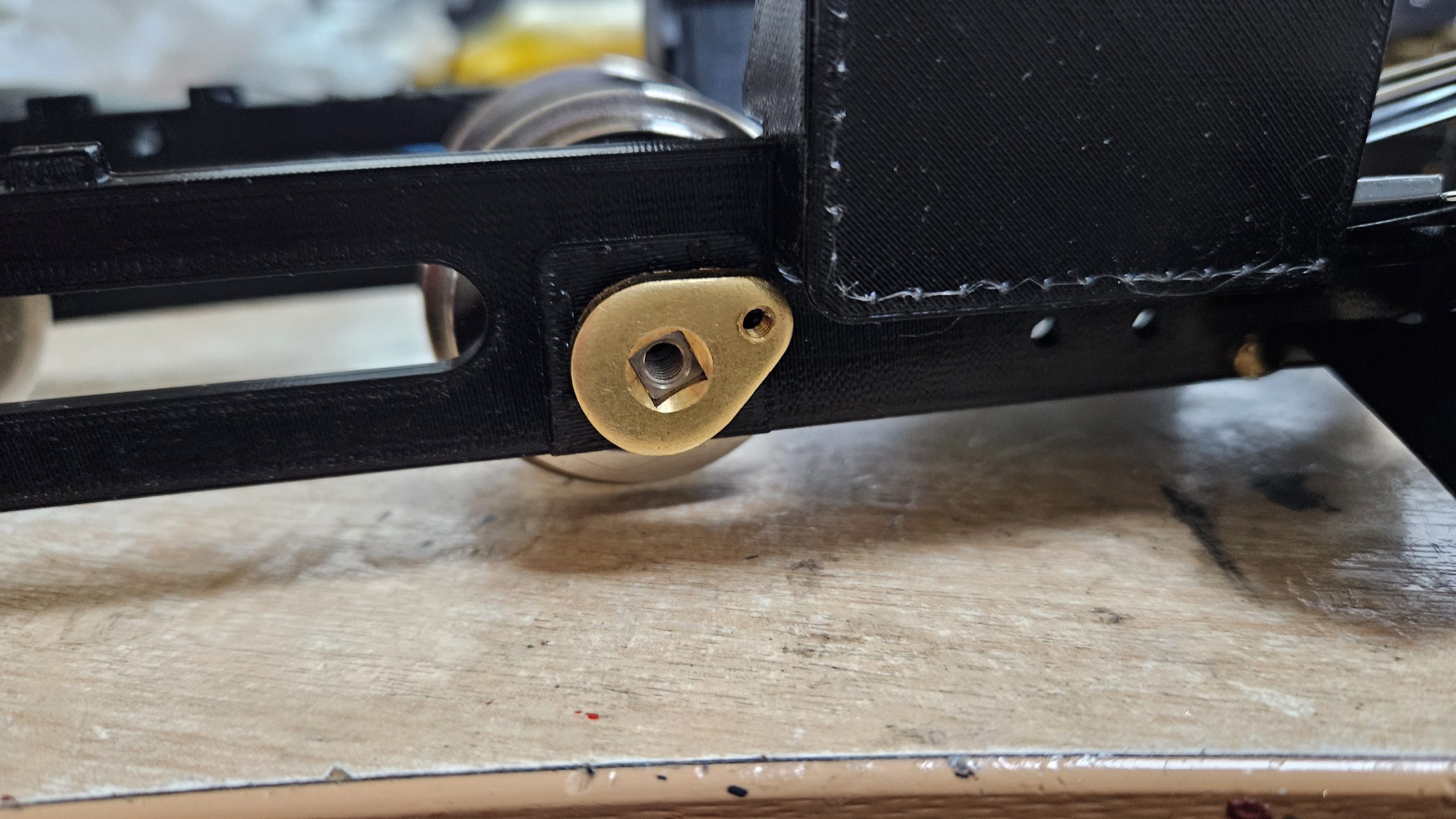
Stage one was the frames. I thought strong left and right hand side frames would be a good start. I’d had good results using Roundhouse axles, wheels and cranks in electric locos in the past, so that was the plan once again. In fact, my “bits box” already had most of the bits I’d need.
I decided to have a strong cross-member between the frames at the front and rear of the loco. These frames would also carry the bufferbeams. The cross members would be fixed to the frames using captive 6 BA nuts and cheese head screws.
The cab would be made up of the front sheet, back sheet, two sides and a roof. I super-glued this together but left the roof removable as a “push” fit. I also decided that the backsheet would be removable. My thinking was that this might be the way to change the battery, which would be inserted via a removable boiler backhead and sit inside the boiler.
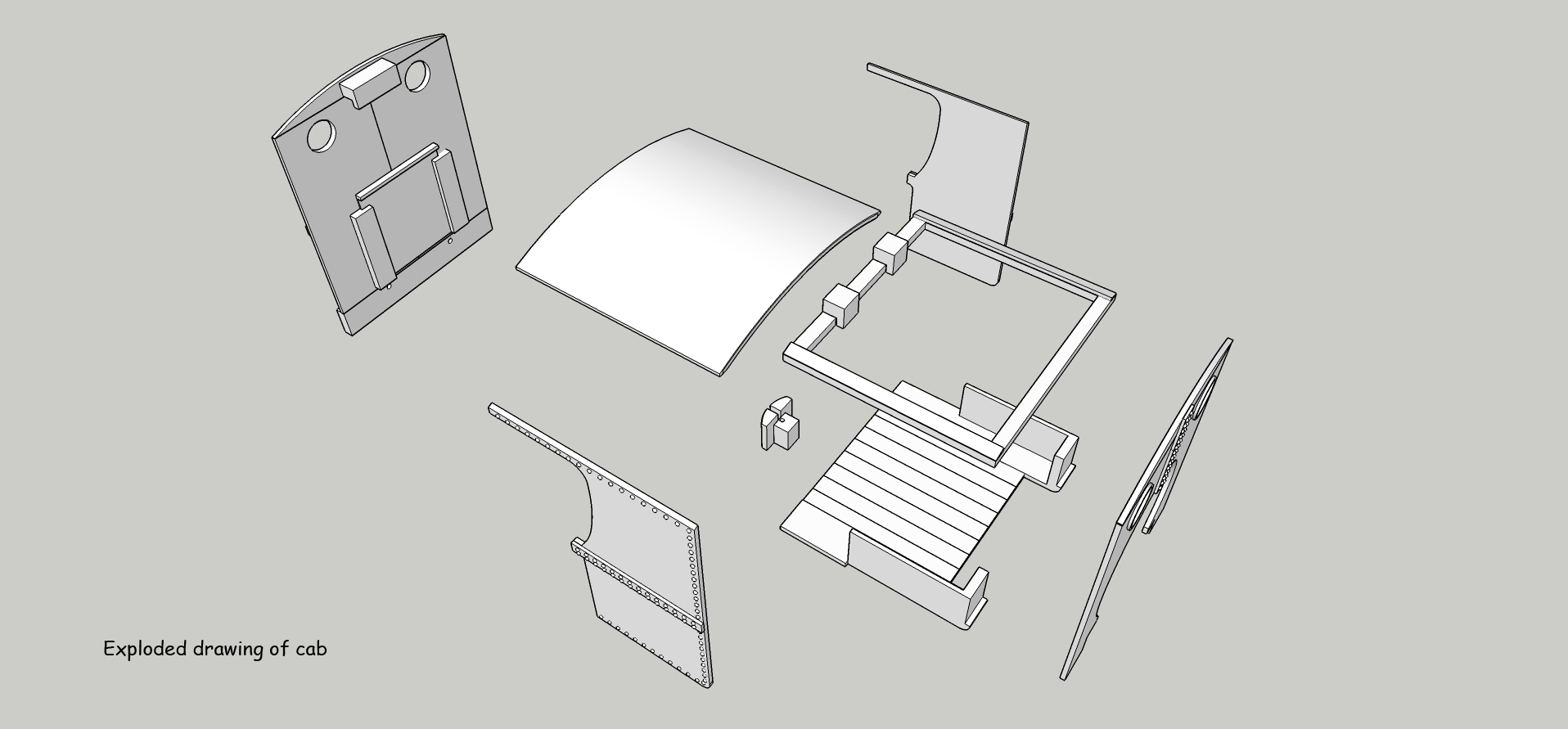
My design had a clip at the top of the backsheet to locate it correctly under the cab roof and two 8 BA screws through the bufferbeam to hold the backsheet in place.
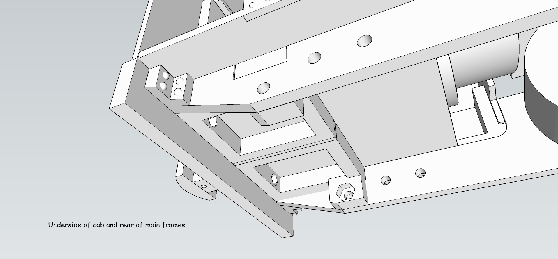
As expected, the frames under the cab were a real Achilles’ heel , it seemed to be an unduly weak spot in the whole design. I didn’t want to stray too far from the drawings of the prototype, so I soldiered on as best as I could!
Starting to assemble the printed parts and test fitting the battery, it became all too obvious that the boiler would have to be cut away somewhat on its underside so that the boiler and battery could clear the tops of the wheel flanges. I was using Roundhouse 33mm dia driving wheels rather than the 32 mm called for to match the prototype… but that was a compromise I was prepared to accept.
The cut-away boiler wouldn’t be too obvious, and once hidden under/inside the large saddletank no-one would be the wiser!
I gave the matter of the saddletank design a lot of thought. I decided to try making the whole tank “top” removable. If I fixed the tank front and back plates to the main frames, the tank top might be able to be “sprung” into place and cunningly held there by integral clips. This would allow easy access to all the electronics and the water vapouriser (I hoped!).
With all the bits printed I tried a “dry assembly” and things looked positive. One thing didn’t look right compared to the original drawings that Alan had provided… I seemed to have made the saddletank too long, so this was reduced in length by 10mm. The new design looked much better.
The tank front, complete with smokebox door, was glued to the front frame stretcher and made for a very robust sub assembly. The saddletank top clipped into it pretty well, and then the tank rear plate complete with boiler was clipped into place to see how it all looked. I made the boiler a generous length to allow for adjustment with any excess hidden inside the cab.
A critical consideration was to have the saddletank front and back plates exactly the correct length apart, otherwise, when the tank top was clipped over them, a nasty gap would be seen! Gluing a floor into the tank was an obvious solution, but I didn’t want to do this at this stage as it would limit my choices when it came to adding the motor / worm drive and the electronics.
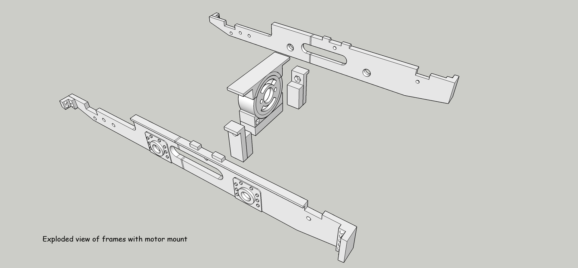
The motor sits in its own cross-member assembly between the locos frames right in the centre of the loco between the two axles. This gives a great deal of strength to the frames.
Quite where it would sit, particularly how low it could sit, would be unknown until I’d added the worm to the motor and the driven gear to the axle. Both jobs needed a bit of work on the lathe, and as my lathe is in the shed and it was snowing at the time, I didn’t want to undertake this bit of engineering until later (preferably when the sun was shining). So…. how to fix the tank front and back plate together but still allow for some adjustment?
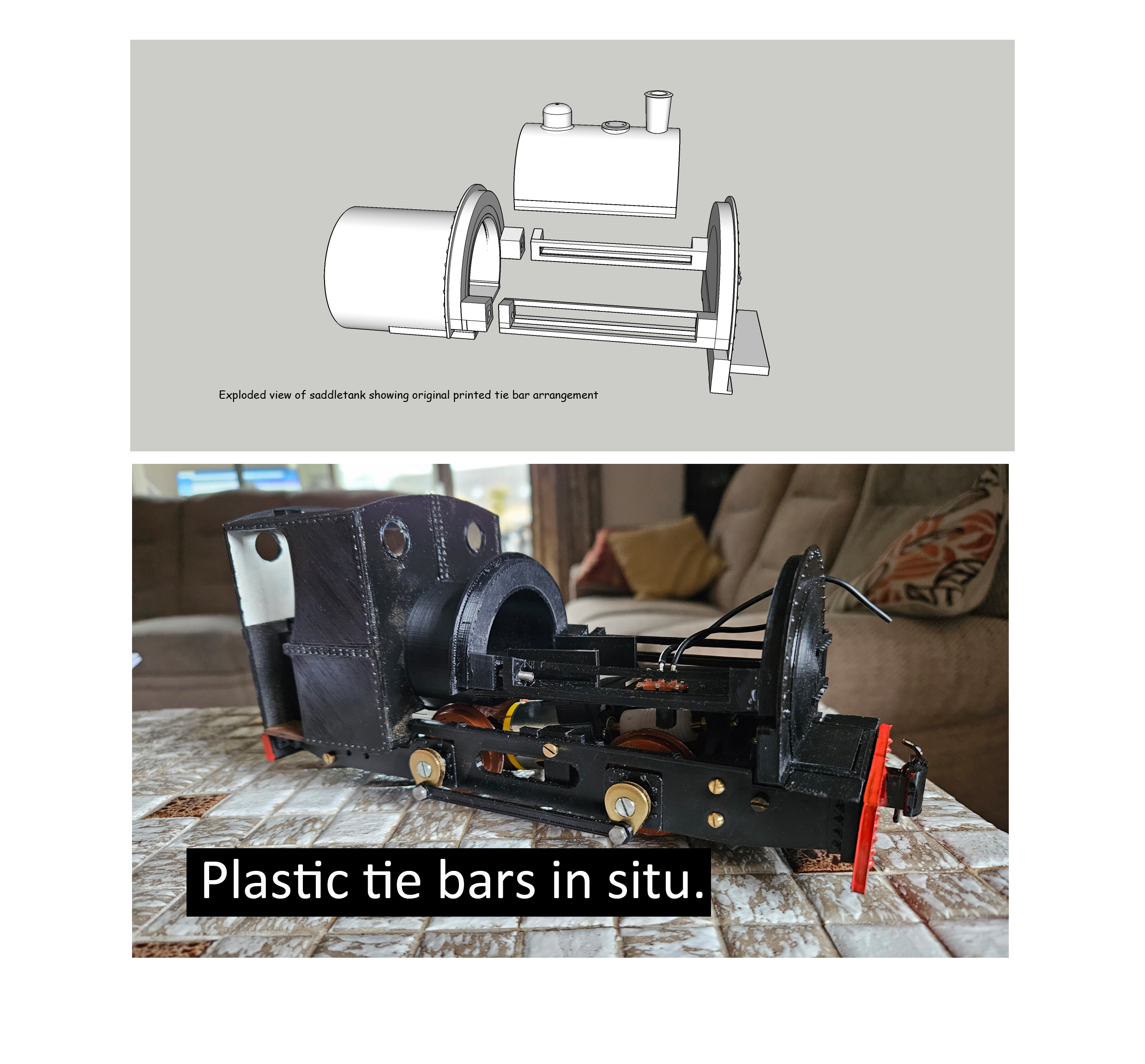
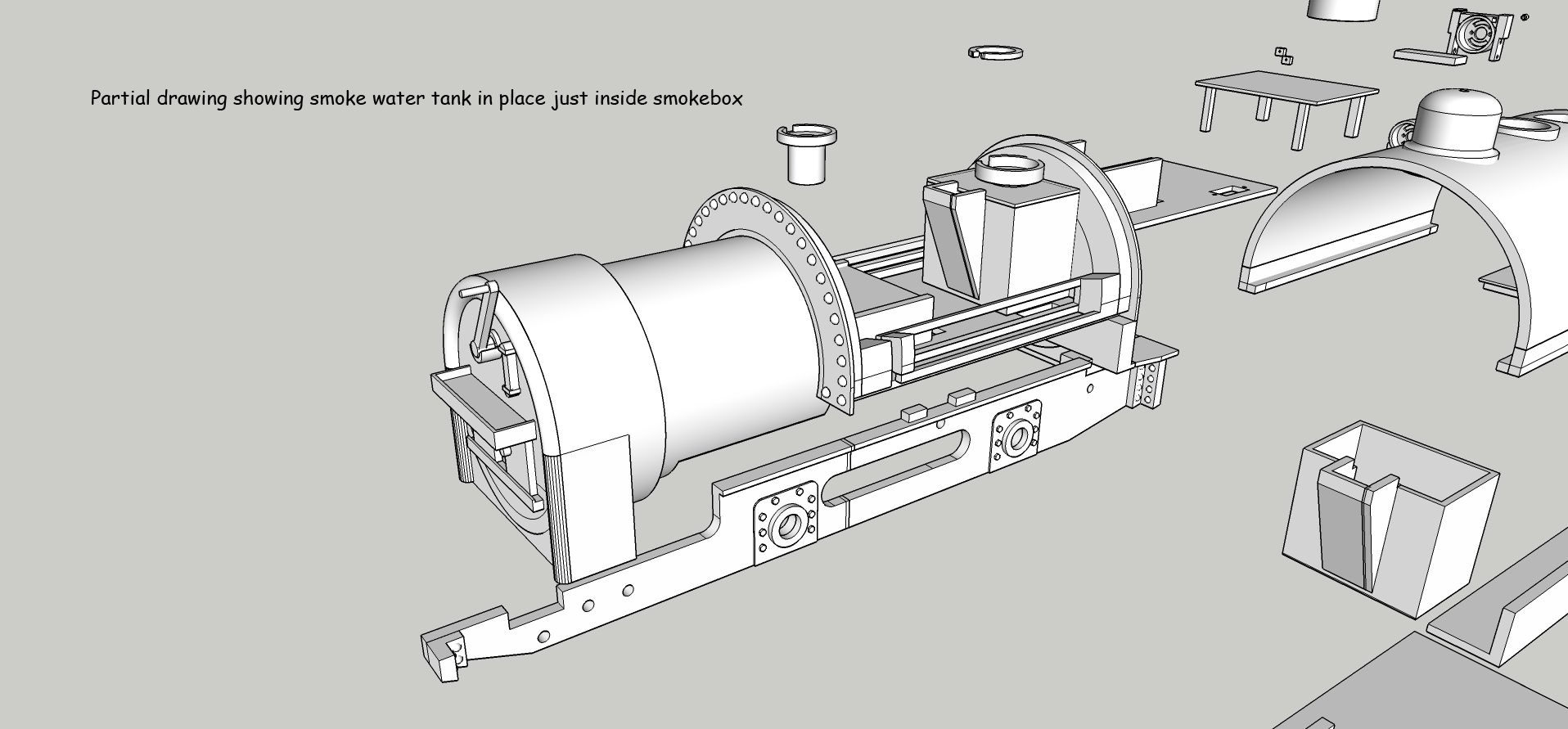
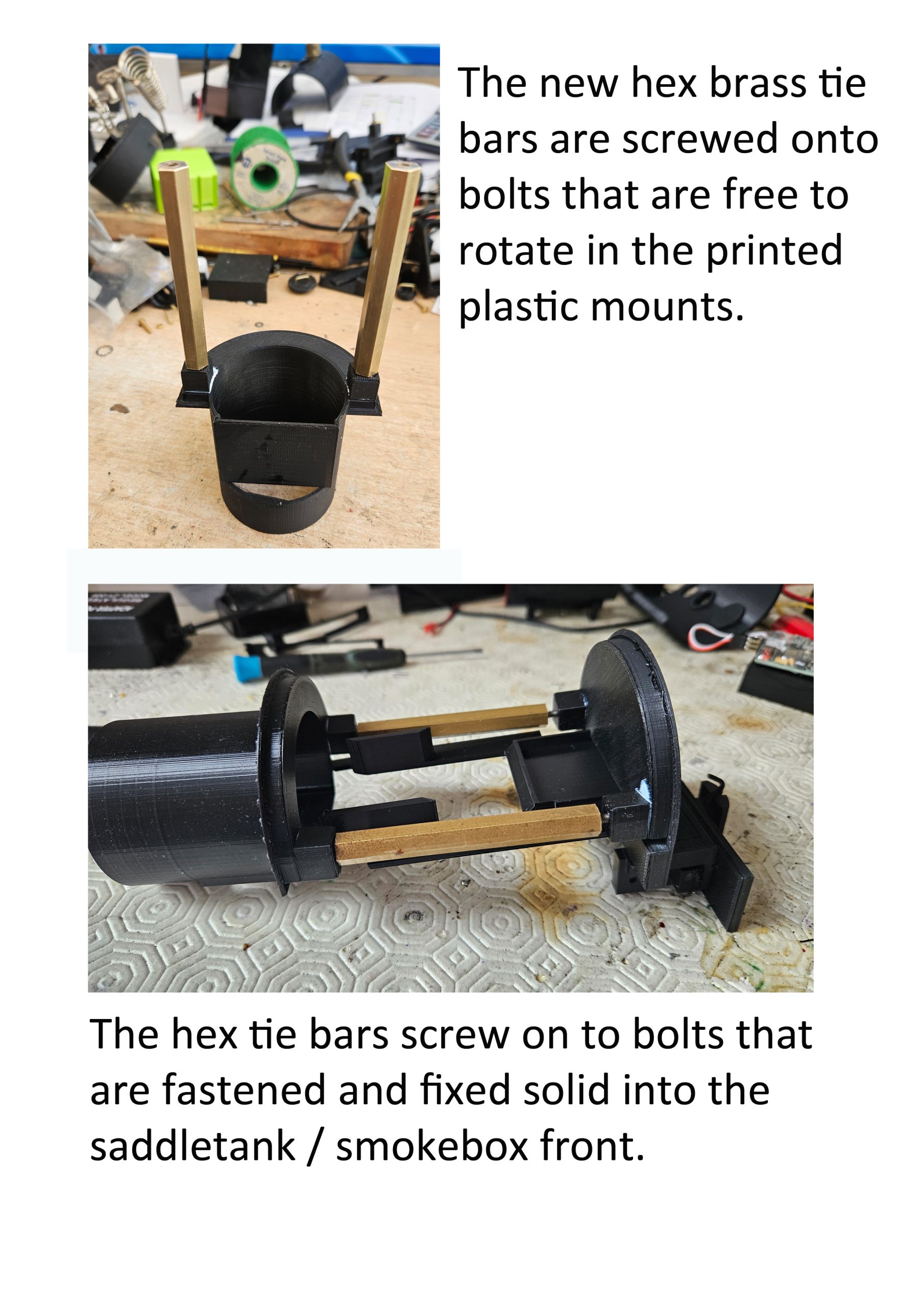
I decided on a system involving tie-rods between the two tank plates. A nut on a long screw would allow me to pull the two plates together to achieve a perfect fit to the tank top (or would it?). Keeping the tie rods to the edge of the tank would also leave a lot of space within the tank for all the “gubbins” I planned to install. The image below might give you a better idea of what was going on.
I’d been awaiting a delivery of a few bits I needed from Roundhouse. When these arrived I added the wheels to the axles and screwed the cranks in place with the usual quartering. Now came another issue I hadn’t envisaged… the cranks missed the front edge of the cab by a fraction of a mm.. or did they? The Roundhouse cranks were larger than those on the de Winton drawings, and I hadn’t appreciated that!
I re-drew the frames with the rear axle 8mm further forward. This gave the de Winton a wheelbase of 4 feet 6 inches rather than 5 feet! Should I move the front axle 8mm further forwards too? And what would this do to the rear overhang?.. Would it overhang too much and “wag its tail”?
A consultation with Alan followed. Actually, the crank just missed the cab and if I was careful with the size of the coupling rod bearing, that did too!!
So in the end it was all left as originally drawn.
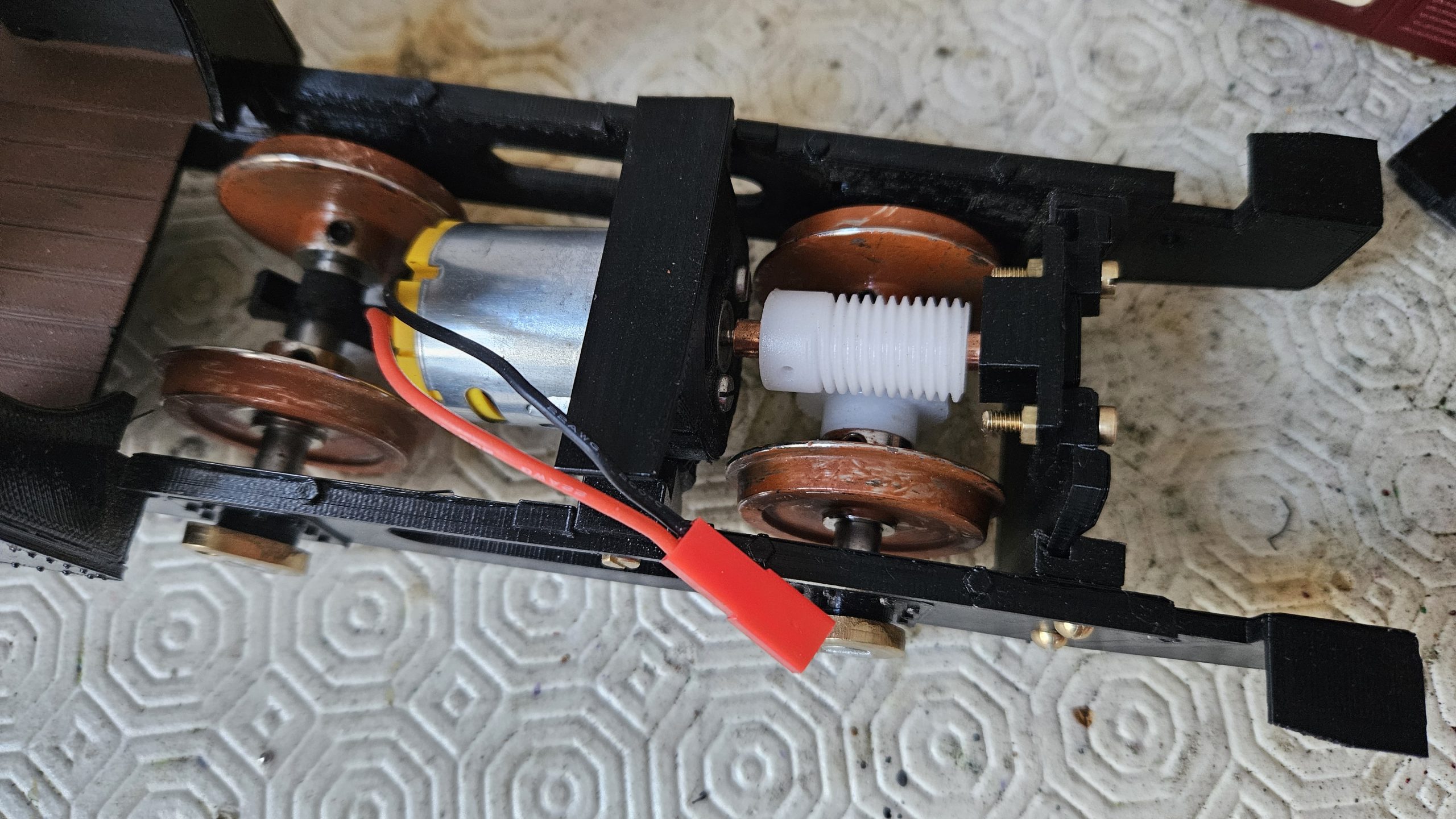
Next comes the fitting of the motor, worm and gear. This is a difficult bit that has to be right if the loco is to run and hopefully perform well.
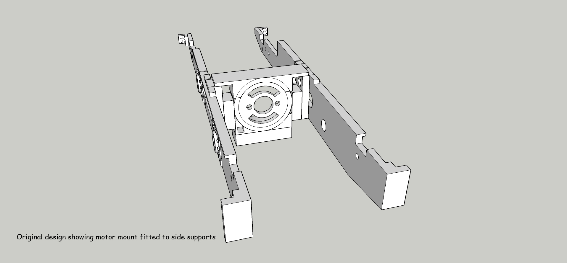
I have a 3d printed standard “holder” that fits over the end of an MFA 360 5 pole motor (4.5 – 15v DC). The motor slots into the holder and then is screwed into place with two small, metric cheese head screws (M2.5 if I remember rightly).
The motor plus holder then slots between 2 side spacers, which bolt into the main frames… but I’m jumping the gun. Here’s an exploded graphic showing the arrangement.
Having fixed the motor nose in the “holder”, the worm has to be fixed on the motor shaft.
I buy my worms and gears from HCP Gears in Chesterfield.
The worm is part ZW0.5-1 (Delrin Plastic, 0.5 MOD) Bore 5mm
The gear is part ZM0.5 40 (Delrin Plastic, 0.5 MOD, 40 Teeth) Bore 6mm
MOD is short for “modulus” and this defines the design of the teeth.
I quote:
Gear modulus (or module) is an ISO standard metric unit defining the size, height, and thickness of gear teeth based on the ratio of pitch diameter to the number of teeth. It indicates tooth size; a higher module means larger teeth, while a lower module signifies finer, smaller teeth. Gears must have the same module to mesh properly.
If readers would like to know more, the relevant web page is here: https://www.hpcgears.com/pdf_c33/15.6-15.9.pdf
Annoyingly the hole in the worm (5mm dia) is much larger than the motor shaft (2.3mm dia) so I have to turn and drill a brass sleeve to fill the gap. This sleeve also extends the motor shaft A LOT so to help take the sideways thrust I mount a “bearing” or pressure pad onto the shaft at the opposite end to the motor. I use superglue and a pin to hold the sleeve to the motor and worm…. so once in place, it ain’t coming off again! Just for reference, the shaft was 35mm long and 5mm in diameter.
By the way, I would much prefer to attach the worm and gear using grub screws…. but cutting small, fine threads into nylon isn’t my forte. Why don’t I use steel worms and gears? Cost!!
(Subsequent note…. We found that drilling the shaft to 2.3mm caused it to be oversize. Drilling to 2.2mm was a great interference fit, largely due to the brass shaft expanding as it gained heat during the drilling process!).
The hole in the gear (6mm dia) has to be drilled out to take the ¼ inch (6.35mm) dia Roundhouse axle. There’s a handy boss on the side of the gear and I drill and pin this to the axle.
With the worm and gear fitted, I drop the motor assembly into the frame and see how it best lines up.
The objective is to keep the motor as low as possible in the frame, so as to keep the space above it free for other “gubbins”. With the optimal position decided (and the worm not too deep in mesh…. we’re looking for the “Goldilocks” spot here) the motor assembly is glued the side spacers which have been screwed to the main frames. Once the glue has set, the motor can be removed from the chassis (if required at any time) by unscrewing the side spacers.
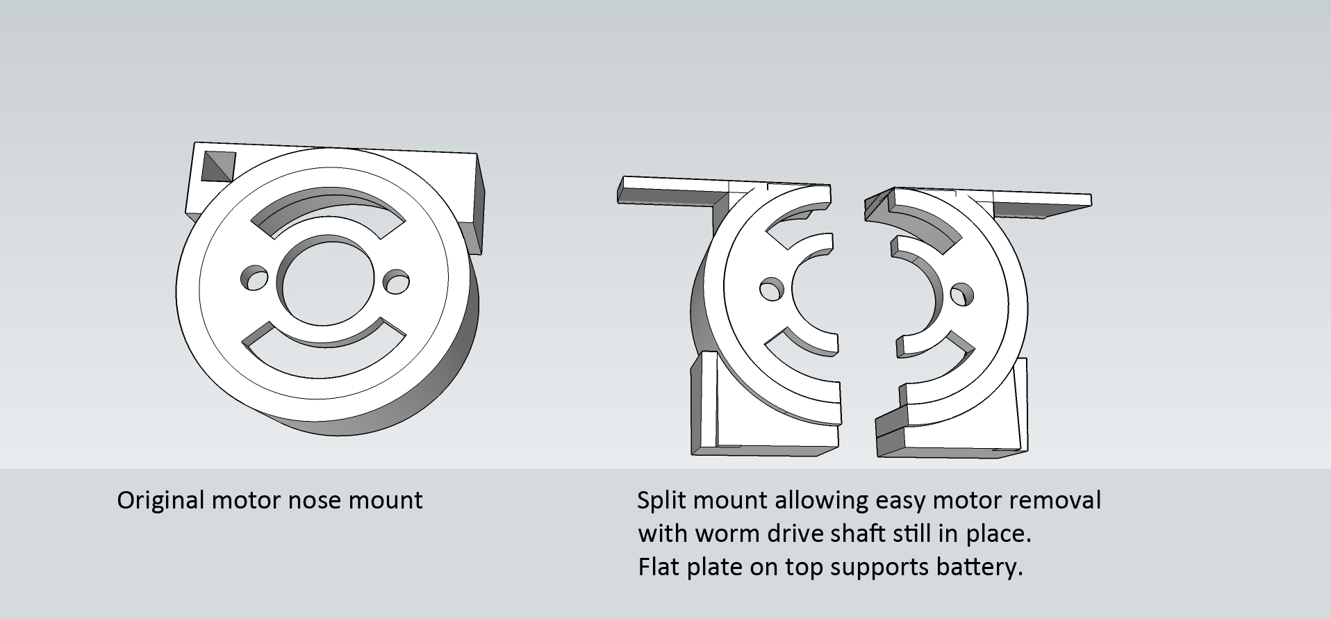
There’s one major drawback to all this, and that is that once the worm is mounted on the motor (and as I’ve mentioned, I usually glue it in place) the shaft and worm can’t easily be removed. Using an interference fit rather than glue worked well, but once again if I needed to disassemble the arrangement I had a problem. I couldn’t heat up the assembly to get the extension shaft off the motor without the heat destroying the nylon worm, and it wouldn’t do the motor much good either! To help in any future dis-assembly process I decided to re-design my motor holder so that it split into two parts, allowing the motor, extension shaft and worm to be re-worked if necessary.
Alan wanted his loco to be controlled by Fosworks (using the receiver FRX22V and electronic speed controller ESC 160) as this would match his existing handset/transmitter.
The electronics were duly placed under the Saddletank to see how well they would fit. It was very tight, but manageable.
Next, the “chuffing” smoke system….
I had decided to fit a water vapour “chuff” system right from the outset, and now came the challenge to see what would actually fit where. I wanted the water storage tank to sit under the loco chimney and extend towards the saddletank filler point, which would be used to empty and top up the tank by means of a syringe.
I looked at the space available and at the same time started to think about where I’d place the main power on/off switch.
Toggle switches can be fitted as an afterthought by just drilling a hole to fit them. For some reason at present I’m favouring slide switches, and these need a rectangular hole plus 2 screw fixing points… so they are best designed into the 3d print.
The underside of the saddletank looked like a reasonable place to fit the switch, but a bit of measuring and drawing indicated that the battery I chose would have a critical impact on the space available for the switch and smoker. I decided to try the design depicted below.
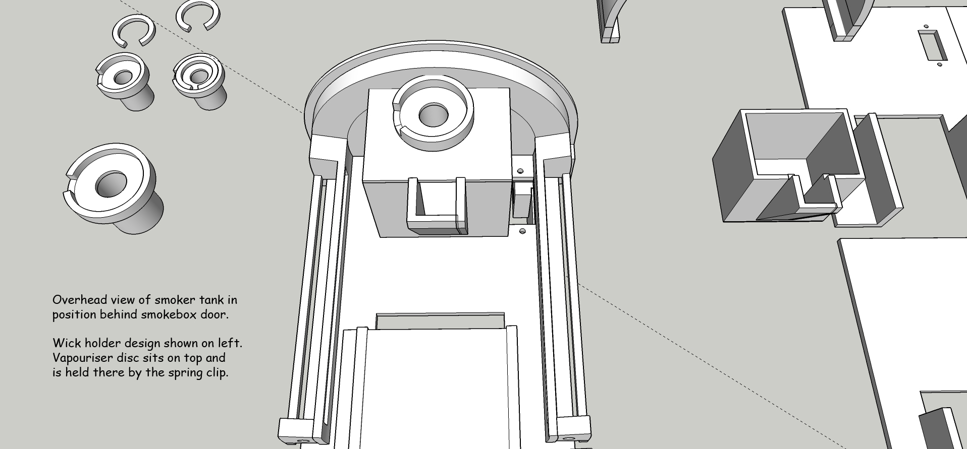
The water tank sits under the chimney with a “chute” for filling, and this reaches back to sit under the water filler point. I narrowed the water tank a little so that the slide on/off switch could sit alongside it.
This approach cut down on the volume of water that the tank could hold, but it left a reasonable space between the battery and the water tank that I might need when adding all the wiring, fuses, voltage step down PCB system, smoker electrics, radio receiver, speed controller, etc. (Generally termed “the gubbins”).
At this point in the design, I hadn’t decided on the size of the battery I wanted to use. A 2200mAh Lipo battery fitted easily with some space. I didn’t yet know how many amps the model would draw, but I estimated that a 2,200mAh battery might give me around an hour’s running time. A 3300mAh (rather longer and wider) battery was a very tight fit, but this might give me around 90 minutes running time. I didn’t intend to run for that length of time, but with a LiPo battery you must not run it down past its re-chargeable point, so better to stay well within the battery’s capacity. I would find the actual drain on the battery once the motor and gears had been fitted and I could run the loco.
Here’s a photo showing comparison battery sizes.
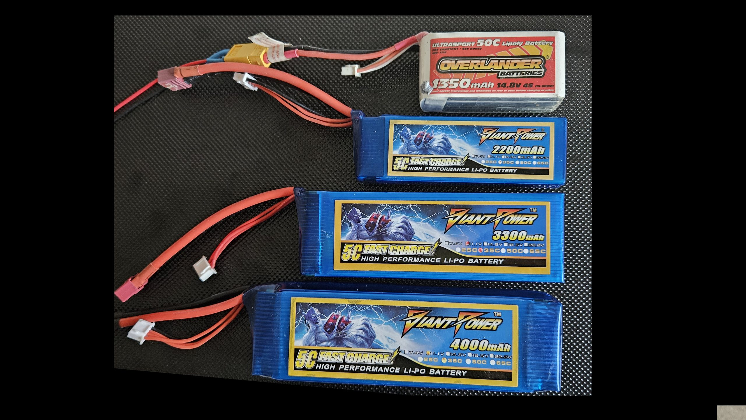
The top battery has a capacity of 1.35 amp/hours, and provides 14.8v
Next comes the 2.2 amp/hour battery @ 11.1v. Both these batteries fit the loco no problems.
Next, the 3.3 amp/hour @11.1v. This would be a very tight fit in the loco.
The bottom battery is 4 amp/hour @11.1v. This has no chance of fitting!
Another factor for consideration was the likely weight of the loco. To be able to pull a “reasonable” train, it would have to have enough weight to keep wheelslip to a minimum. The Roundhouse wheels and axles added some weight, the water for the smoker would add a little more and the battery would add a little more. Previous experience had taught me that a few lumps of steel added somewhere over the wheels was always a good idea, but once again this would take up valuable space and at this stage I wasn’t sure how much spare space I’d have.
To compound the challenge, I would also like to fit a speaker for steam sound effects… but where would this go? For best sound reproduction I would need the largest speaker possible. If it wouldn’t fit under the saddle, maybe it might go up inside the cab roof?
Alan had asked for a Fosworks radio system. I fancied using the Hornby HM7000 DCC system. The latter offers sound features and is much smaller and very much cheaper than most other systems, but it is a bit of an electrical challenge, particularly if the electric motor draws more than 1 amp continuous and 1.5 amps peak (1500mA). I wouldn’t know if this would be a practical problem until the motor and gears were installed.
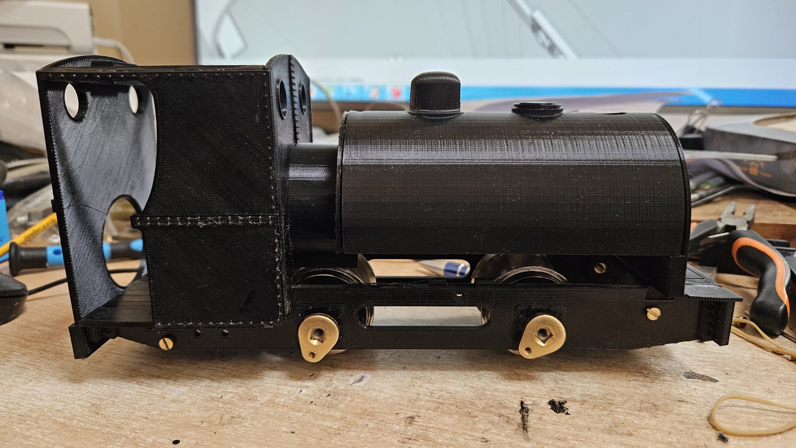
So now came the best bit, screwing all the printed parts together…..
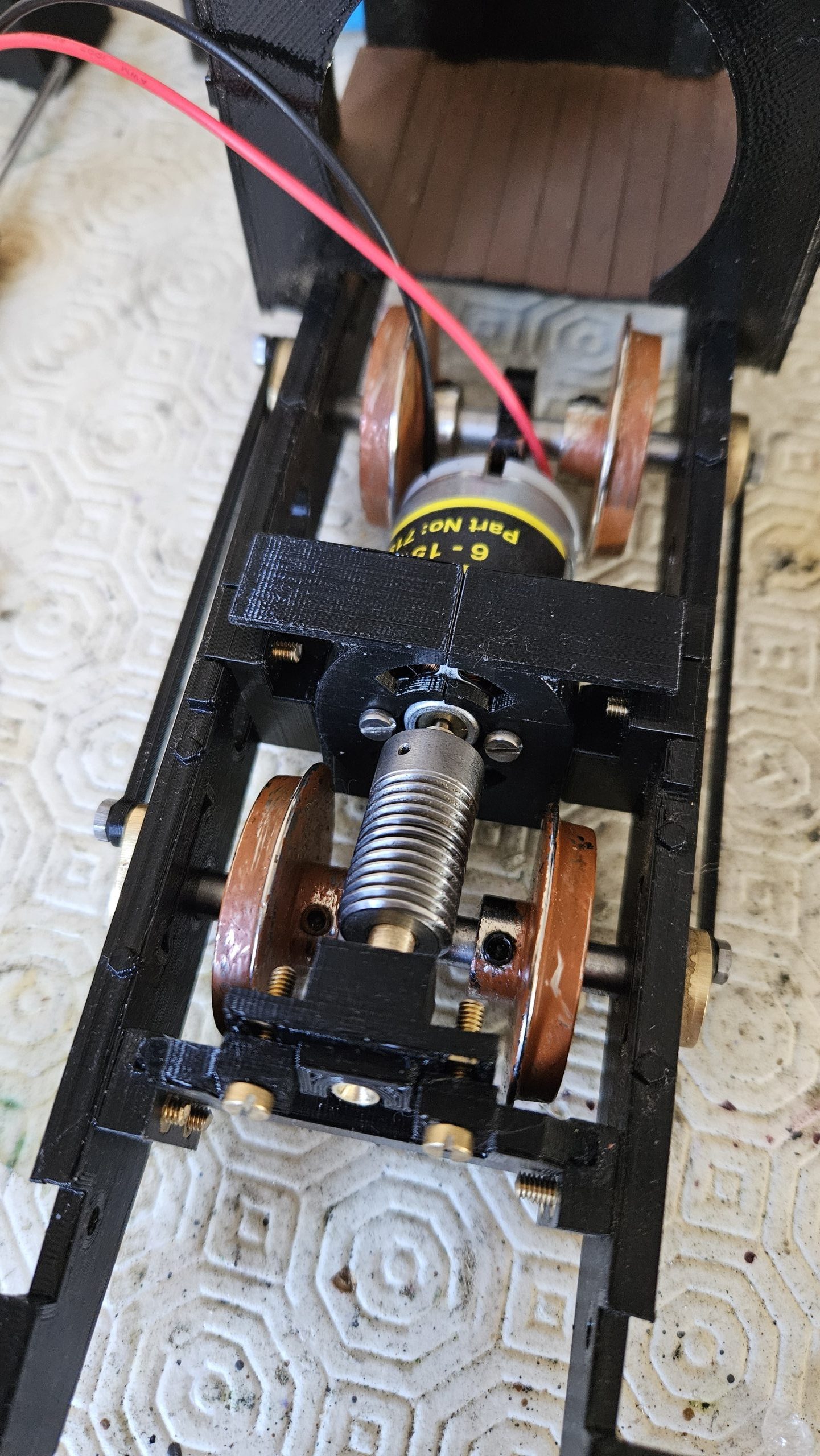
The following photos show the assembly procedure…..
- Chassis complete with Roundhouse axles and cranks. Gear wheel fitted to front axles and optical sensor fitted to rear axle.
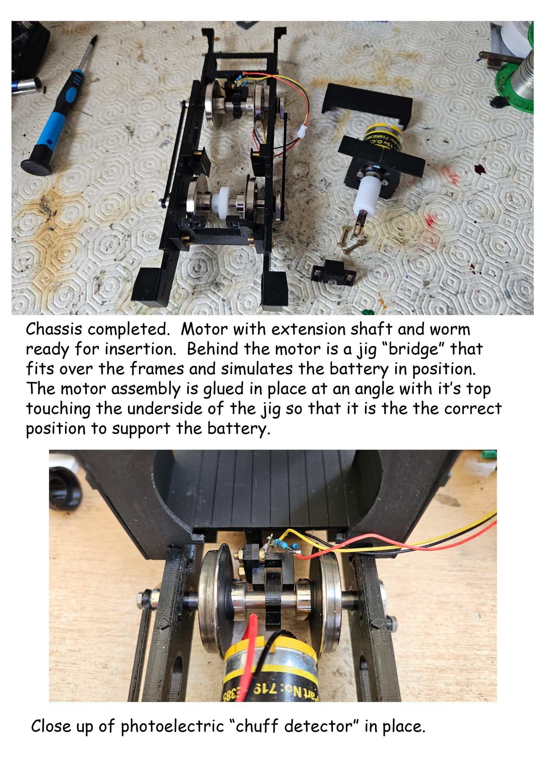
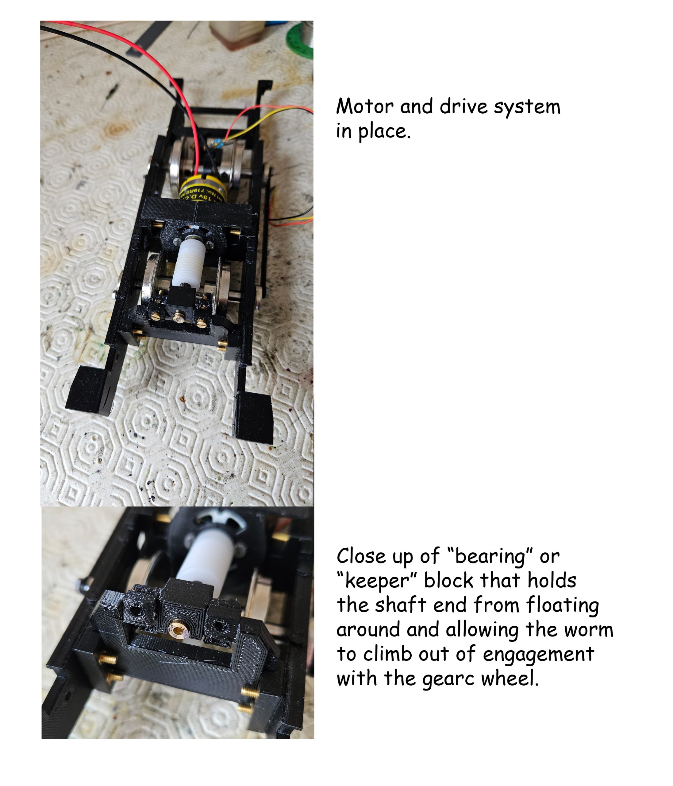
- Motor dropped into place
- Cab and saddletank back fitted.
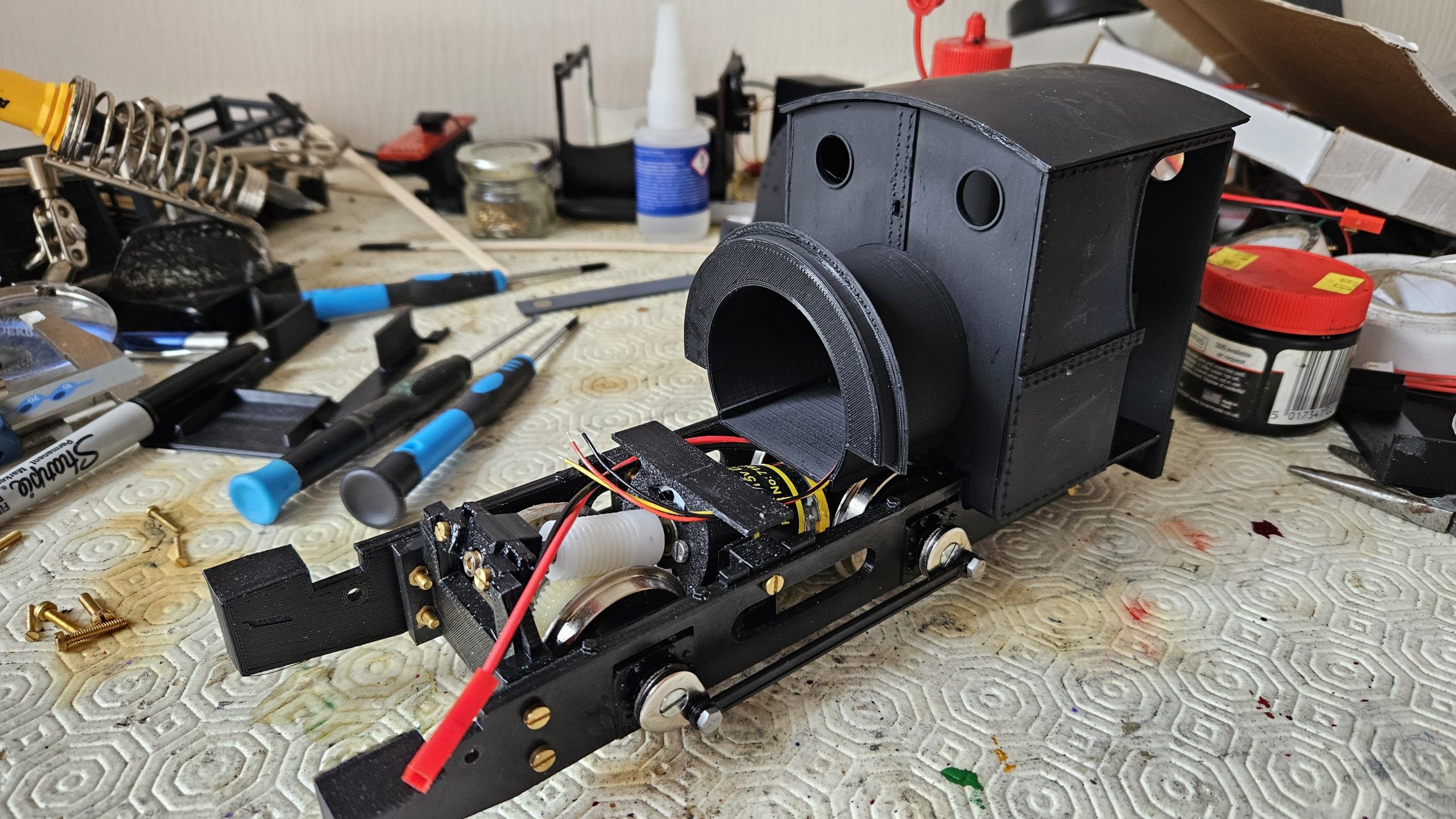
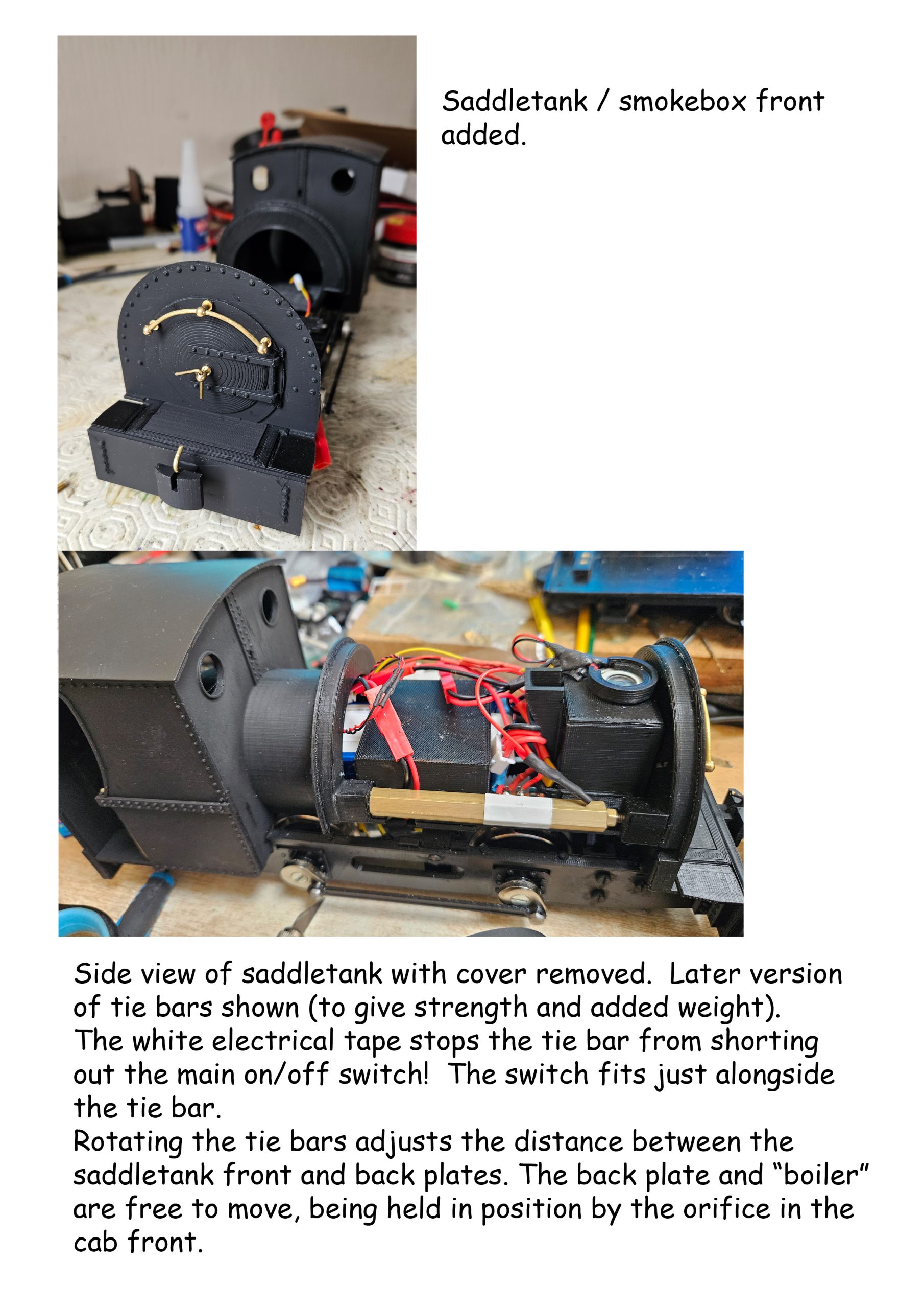
- Smokebox and saddletank front fitted.
- Adjustable tie bars in place holding saddletank front and back the correct distance apart.
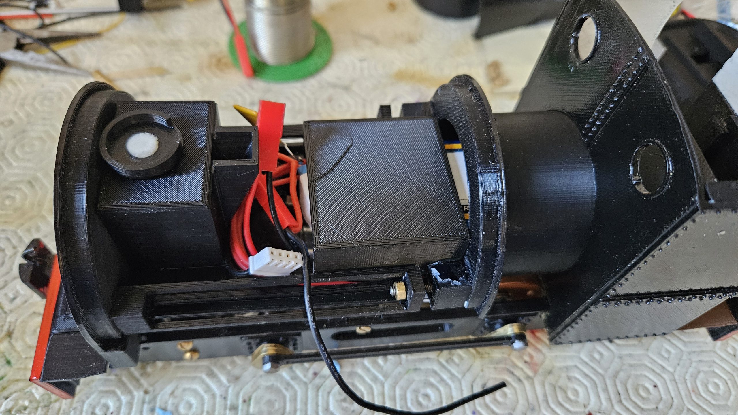
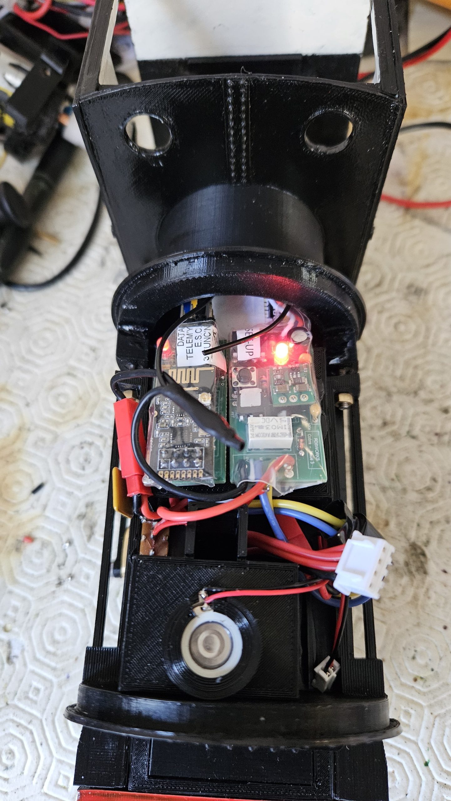
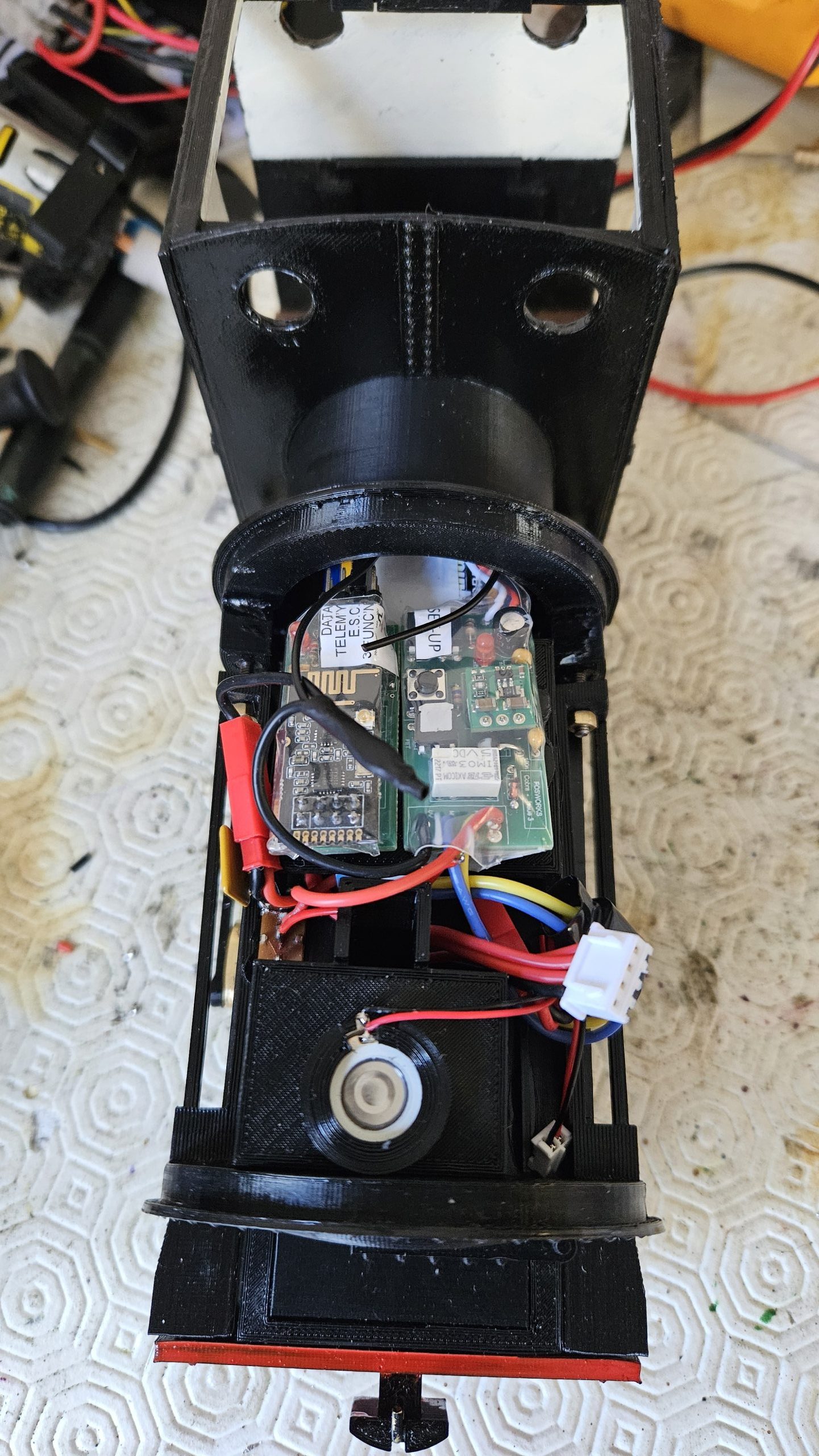
Fosworks radio control and water vapour smoker fitted.
At this stage I made a short video of testing on the bench:
With everything looking promising the loco was taken to be tested on the Huddersfield Railway Modellers Portmadoc layout.
The first problem to be noted was the raucous noise that the mechanism made… it was horrendous and would have to be addressed.
During the test, due entirely to my own fault, I drove the loco over a lifting bridge that was lifted!!! Miraculously, little damage was apparent… but the two tie bars had both snapped and their ends had pulled out of the saddletank . The superglue had held, but the printed plastic hadn’t.
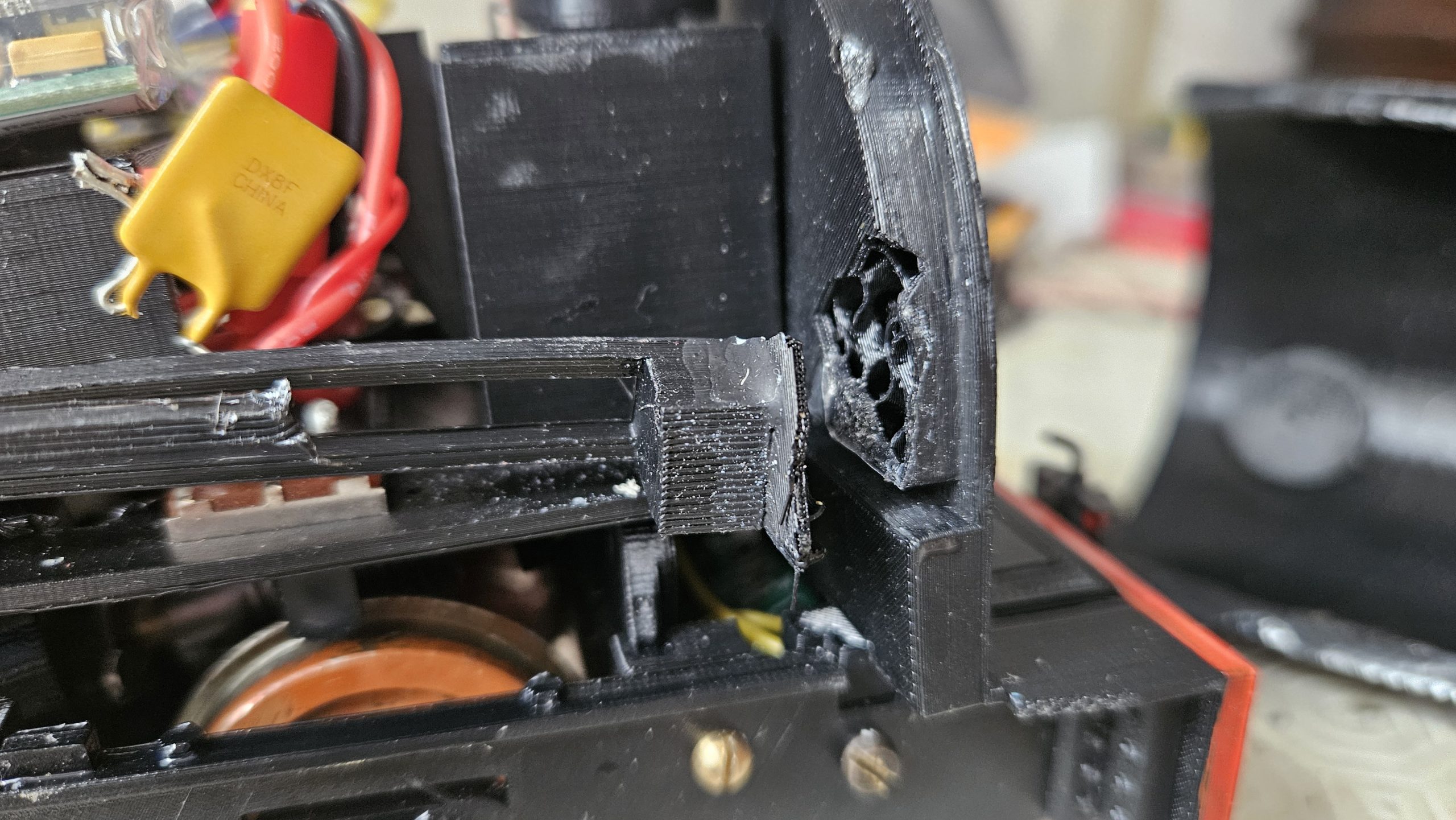
Thankfully, the design had shown how robust it was as the loco could still run… so testing continued.
The second major issue encountered was that the loco was prone to wheelslip. In fact, any more than 3 box vans (6 axles) and the loco just sat with its wheels spinning. Something would have to be done about that.
Here’s a video of the testing at HRM:
Having thought about the two problems (too much noise and too little weight) I decided to make some design changes.
The tie bars had broken in the “accident”, so I decided to replace the flimsy printed design with tie bars made of 8mm brass Hex bar. This would add strength and weight.
What about the noisy drive mechanism? I decided to mount the motor between two vibration absorbing pads. These were made by simply wrapping 6 turns of electrical tape around itself to make a “pad” and cutting an appropriate piece out. These were glued between the two chassis motor mounts and the main motor assembly to try to damp or absorb vibration. The vibration was coming from the long rod that I’d made to mount the worm. Any mis-alignment in the system resulted in an awful lot of noise!
Trying the loco again, the sound had diminished somewhat, but not to the level required. Moreover, the worm and gear immediately produced a fine snow of nylon as the worm climbed out of mesh and ground the tips off the gear!!! The sound absorbing pads had allowed the motor to move in its mounting…. So this needed attention.
Adjusting the “bearing” on the other end of the drive shaft to the motor cured the “snow” problem and kept the worm and gear correctly engaged…. But the whole thing was still very noisy. As a last resort, I added a plentiful supply of thin steam oil to all the moving parts. The sound was definitely reducing… and then miracle of miracles…. oiling the “bearing” on the drive shaft end completely cured the noise problem. I immediately went out and bought a lottery ticket.
I’d also decided that the loco wasn’t producing enough water vapour to warrant all the trouble I’d taken to design and fit the system. I wondered if the wick was held too tightly in its holder, and maybe this was restricting the water that was being “wicked” up? I printed a wick holder with a slightly larger diameter and tried it…. The wick was now too sloppy to be held in place! I’d always used narrow diameter wicks rather than the wider, standard wicks that came with the vapouriser. I had to go with the narrower wicks as they had to fit up some very narrow chimneys… but now that I’d discovered how to fit the vapourisers in the smokebox below the base of the chimney, the wick could be a lot wider…. So I tried a standard diameter wick in the new holder. The result was a huge increase in vapour “steam”!! So, the conclusion was, it doesn’t matter how tight the wick is held, it’s the cross section of the wick that matters. Bigger cross-section… more steam.
When all these mods had been fitted to the loco, the result was a transformation. It ran smoothly and quietly, producing a good volume of steam at the chimney, and could haul a reasonable rake of slate trucks. Alan went away a happy man.
Here’s a short video of Alan’s loco in action before we discovered how to get more steam with a wider diameter wick:
Further Developments....
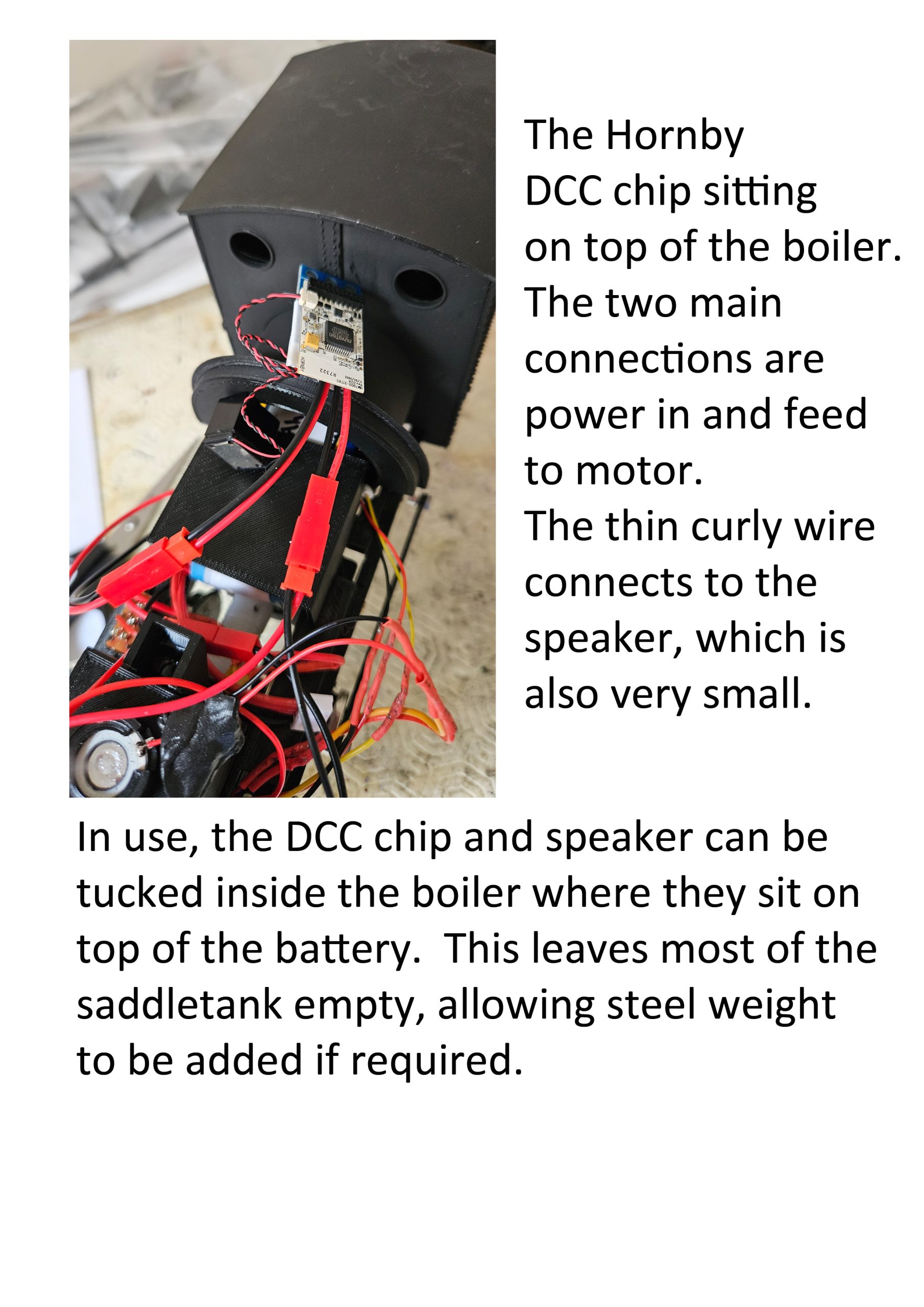
I was so pleased with the finished loco that I decided to print one for myself. For my version, I decided to fit the Hornby HM7000 DCC system so that I’d have complete control of the loco through my smartphone and, as a bonus, I’d have a host of sound effects.
Here’s a photo of the HM7000 installation. The chip is incredibly small so there was a huge amount of room for it in the saddletank. In fact, the chip fitted back inside the boiler space together with the “sugar cube” speaker that Hornby supplies with the chip.
Here’s a short video of the loco in action, courtesy of Mark Hirst at Huddersfield Railway Modellers:
www.facebook.com/share/v/1CqJ7vBF5e/
I’ll be honest…. the completed loco, with synchronised smoke effects and sound, exceeded my wildest expectations.
For a very simple looking loco, this turned out to be a real “magnum opus”. I’m going to take a break from loco building now and just enjoy running it!
(Famous last words!!).