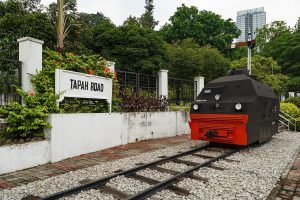
The Malayan Emergency was a guerilla war fought between 1948 and 1960. The Malayan National Liberation Army (MNLA) fought for independence from the British Empire, in order to establish a communist state. One of the main targets for guerilla action was the 1300 mile long metre-gauge railway that ran across Malaysia between Singapore in the south and Thailand to the north. The narrow gauge railway passed through jungle that was ideal for ambush. Consequently, the need for an armoured rail vehicle to protect trains was identified.
In 1952, an order for 42 armoured trolleys was placed with Wickham & Co of Ware in Hertfordshire. The chassis of the armoured trolley was based on the Wickham Type 40 chassis but with stronger springs to support the additional weight of the armour plating. Power was provided by a Perkins P6 diesel engine with a four-speed gearbox driving the rear axle. Designed for a crew of 5 or 6, the 6¾ ton trolley had a driving position at each end of the vehicle, along with gun ports and a swivelling gun turret from an Alvis Saracen armoured personnel carrier.
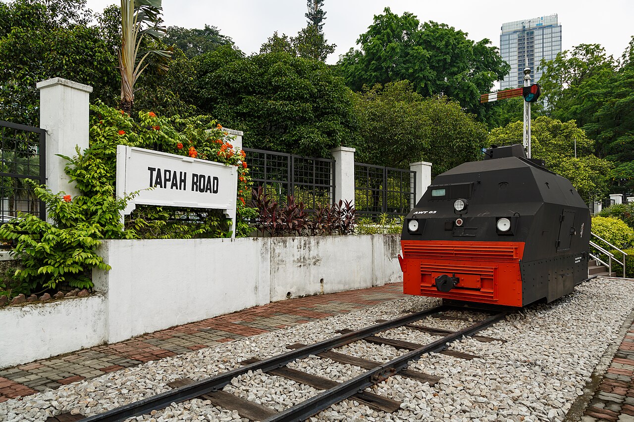
Known locally as the Armoured Wickham Trolley (AWT), one vehicle would proceed ahead of a train to engage any MNLA forces, while a second AWT following behind the train to protect the rear in case of ambush. The AWTs, with a top speed of 60 mph, proved very successful and robust. With the end of hostilities in Malaysia, several vehicles were sold to South Vietnam in 1962 for train escort and mine patrol duties. Between 1953 and 1960, further narrow gauge AWTs were purchased for Burma, Belgian Congo and Portuguese Goa.
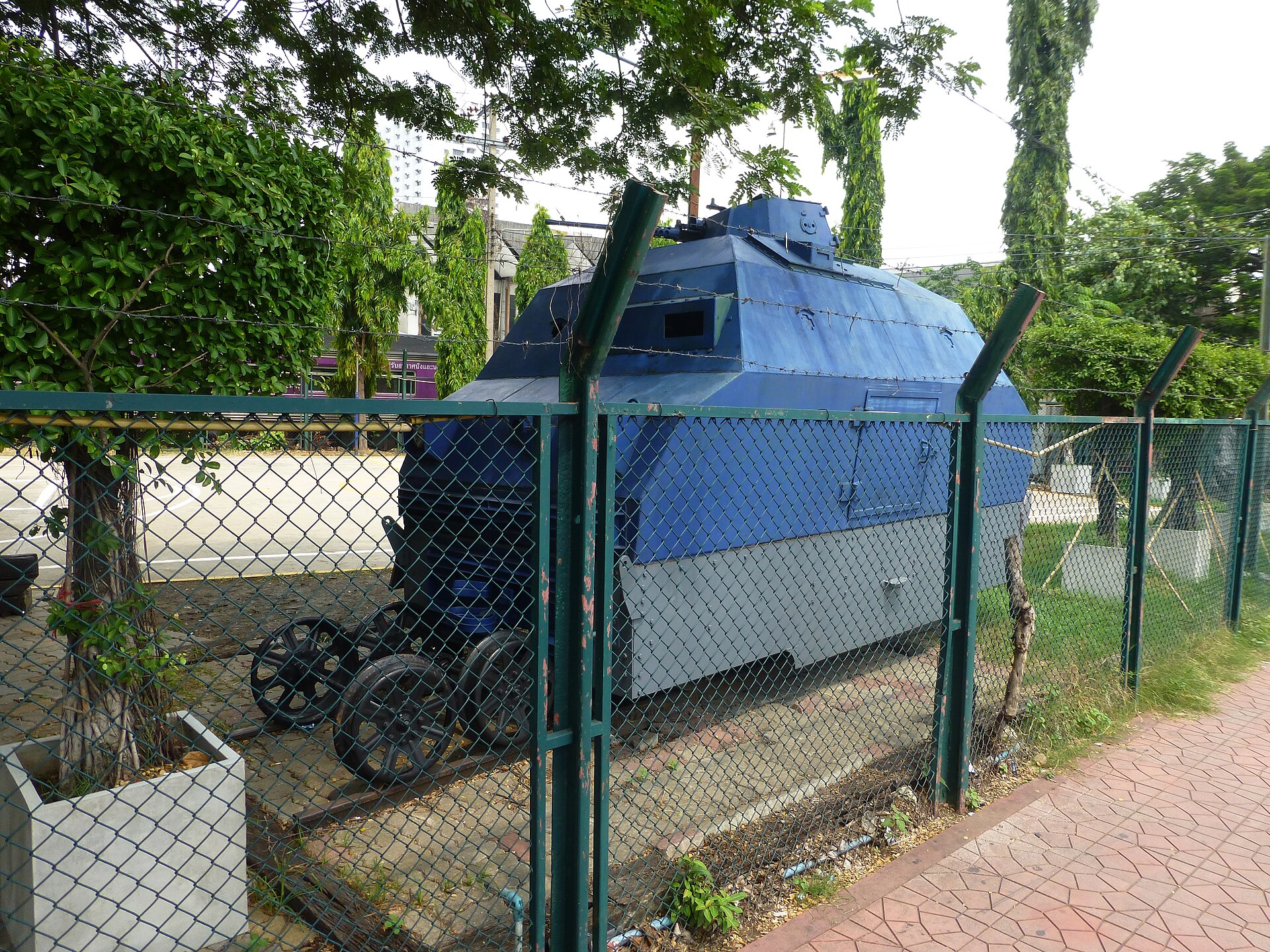
Wickham works numbers indicate that a total of 68 AWTs were built, of which a small number entered preservation. Examples of AWTs can be found at the Royal Malaysian Police Museum and the Tunku Abdul Rahmann Memorial in Kuala Lumpur, the Malaysian National Army Museum in Port Dickson plus the Police Headquarters and the old Bankok Railway Station in Thailand. The original livery of the Malaysian AWTs was battleship grey, while the Portuguese and Burmese units was dark green.
Armoured Wickham Trolley – Making the Model
Alan Poxon seems adept at finding unusual, weird and wonderful prototypes to model.
“How do you fancy making one of these in 16mm scale?” he asked, passing me what I thought was a toffee.
In fact, it was a 009 scale loco bodyshell printed in resin for something that looked like an armoured car, but on rails.
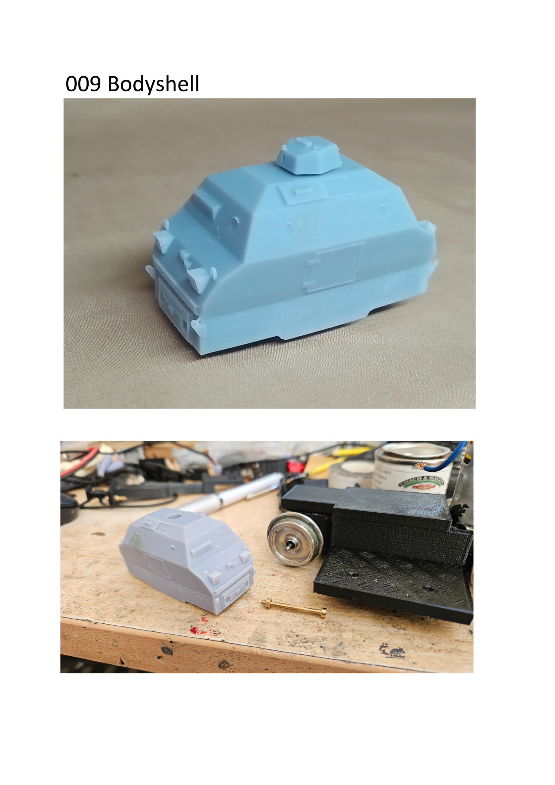
He explained that it was an armoured Wickham trolley, made for use during the Malayan Insurgency (also known as the Malayan Emergency) which was a conflict fought between 1948 and 1960.
Examination of the 009 (4mm scale) bodyshell, together with drawings and photographs that Alan supplied, indicated that the loco was mainly of welded construction and that the body consisted of lots of flat plates at various angles. The geometry of it all looked fairly simple, and as a bonus there were only a few rivets to add to give the model some detail. Most of the structure seemed to be of welded construction.
“It’ll be quite a big model” Alan warned… and he was right.
“I’ve got an old Swift 16 motorised 4 wheel chassis that has just the right wheelbase and wheel size” he said. “You can use that. It’s set at 45mm gauge but that suits the loco as the prototype was metre gauge…. And I’ve an old Timpdon-style radio… that’ll do for it too”.
So, I duly took it all home and sat down to ponder. I three d print in filament, so the prints ideally need to fit flat on my printer to get best results. Angled prints often show the lines of the layers they are built up of. (Actually, I must treat myself to a new printer one day… my Prusa Mk3 is getting very long in the tooth and it seems that more modern machines can produce much better prints… but that’s another story).
The various angles of armour plate on the model caused me some concern. Ideally, I’d prefer to print all the plates flat to get the best surface finish, so that would mean starting with a printed framework or skeleton of the complete loco onto which I’d add each printed plate… gluing the PET-G printed plates on with Superglue. I imagined that this would be quite a challenge, and might produce a bodyshell that would be somewhat less than robust.
I started to draw the loco body in Sketchup, which everyone says is not really suited to the job, but hey-ho…. I’ve always ploughed a lone furrow!
The best (i.e. easiest!!) way to establish the shape of the loco seemed to be to slice the design into 4 parts horizontally. This would produce “Layers”, each of which would then have a reasonably simple geometry and I could print each layer separately then glue the lot together.
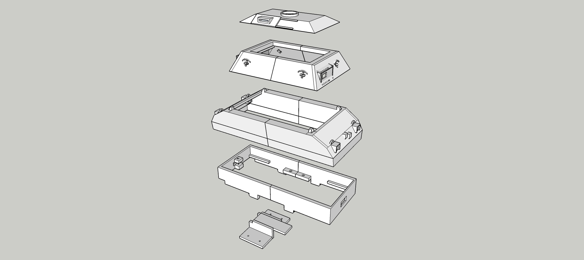
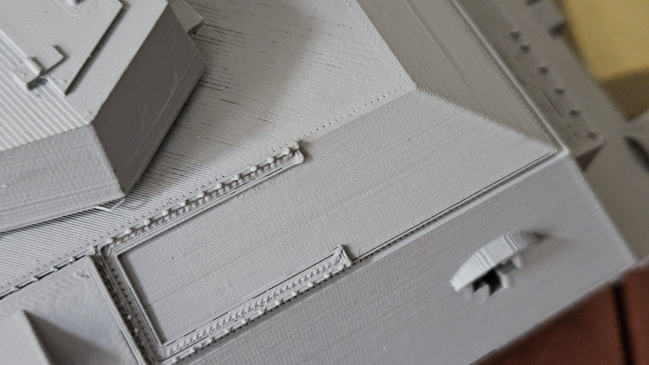
Rather than go for the “Skeletal frame with printed flat plates” approach I decided to risk printing each layer flat on the printer build plate, so the multiple angled faces of the sides would be “grown” up from the build plate at various angles and might exhibit some bad layering. I did a test print of the top or “roof” layer, and the results looked acceptable… so I decided to go with this approach as being much simpler than the skeletal frame idea. I thought that the printed layers would also result in a much more substantial, robust loco.
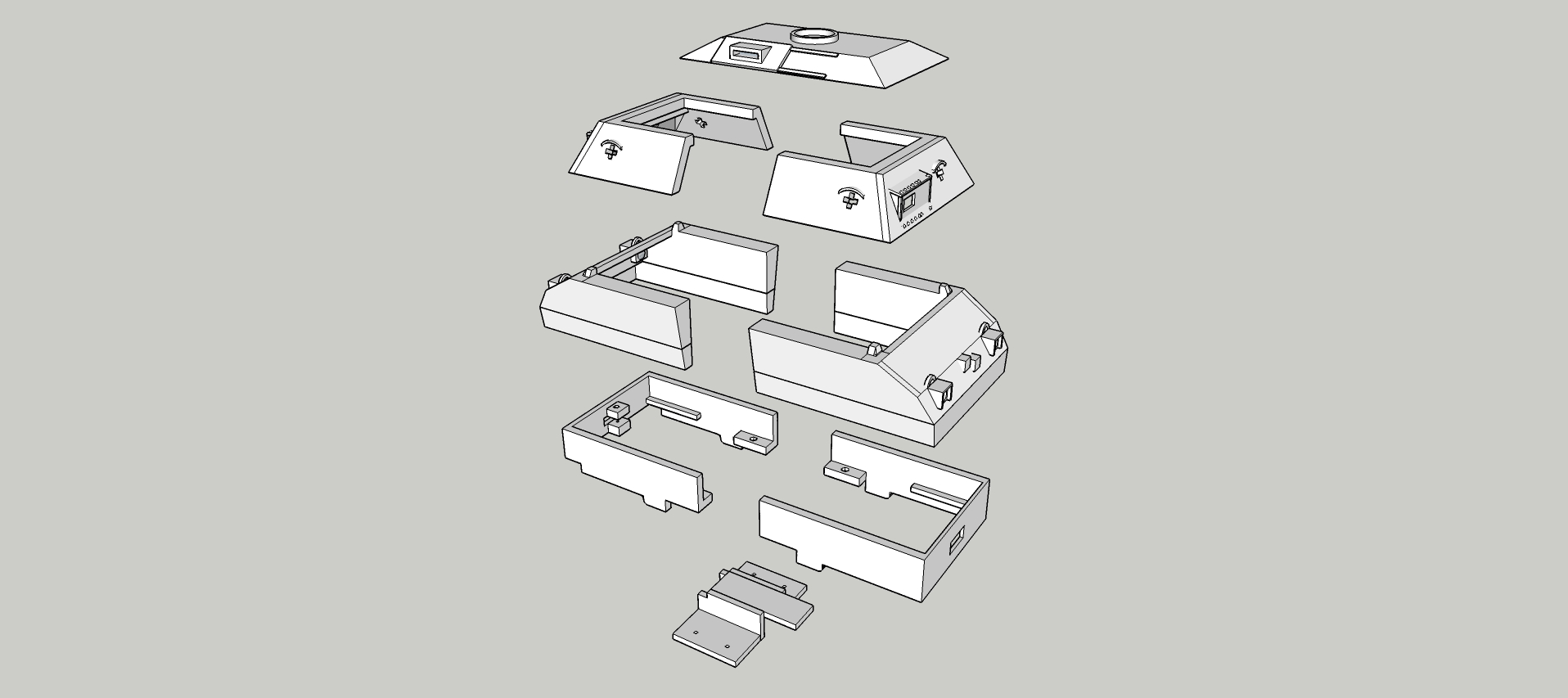
Even splitting the design into horizontal layers, three of the four layers were too big for my printer to cope with so I had to print each layer as two halves. Luckily, the loco design is a bit of a “Janus” in that it has two identical ends (the loco can travel in both directions, a bit like a double Fairlie). When I say identical, they are actually a mirror image of each other, but my design software can sort that out at the push of a button.
Alan was quite right, it’s a big loco. Each half of each layer took around 5 hours to print (mostly overnight) and took plenty of filament. Some parts were rejected when I realised that they could be improved upon, but that’s what prototyping is all about.
Luckily, the real loco had seam lines between the various armour plates, so if my model included obvious lines where the various layers and halves had been glued together, it didn’t matter as long as the real thing also exhibited these lines. It did matter, however, if I butt-jointed the halves and the Superglue exuded from the joint. It looked awful and another 10 hours of printing was thrown in the bin! I decided to print some supporting flat plates which would be glued inside and overlap the butt joint… keeping glue away from the exterior of the model. This produced an acceptable result.
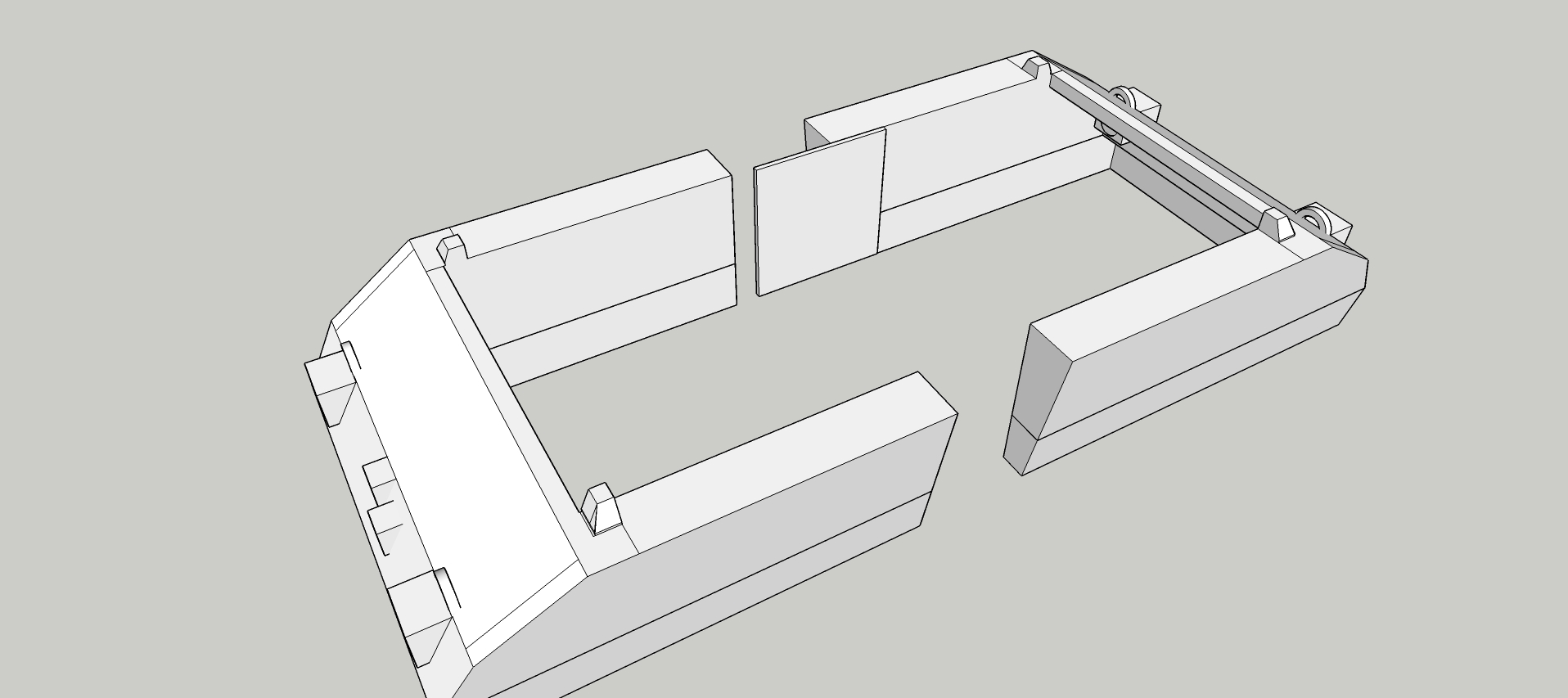
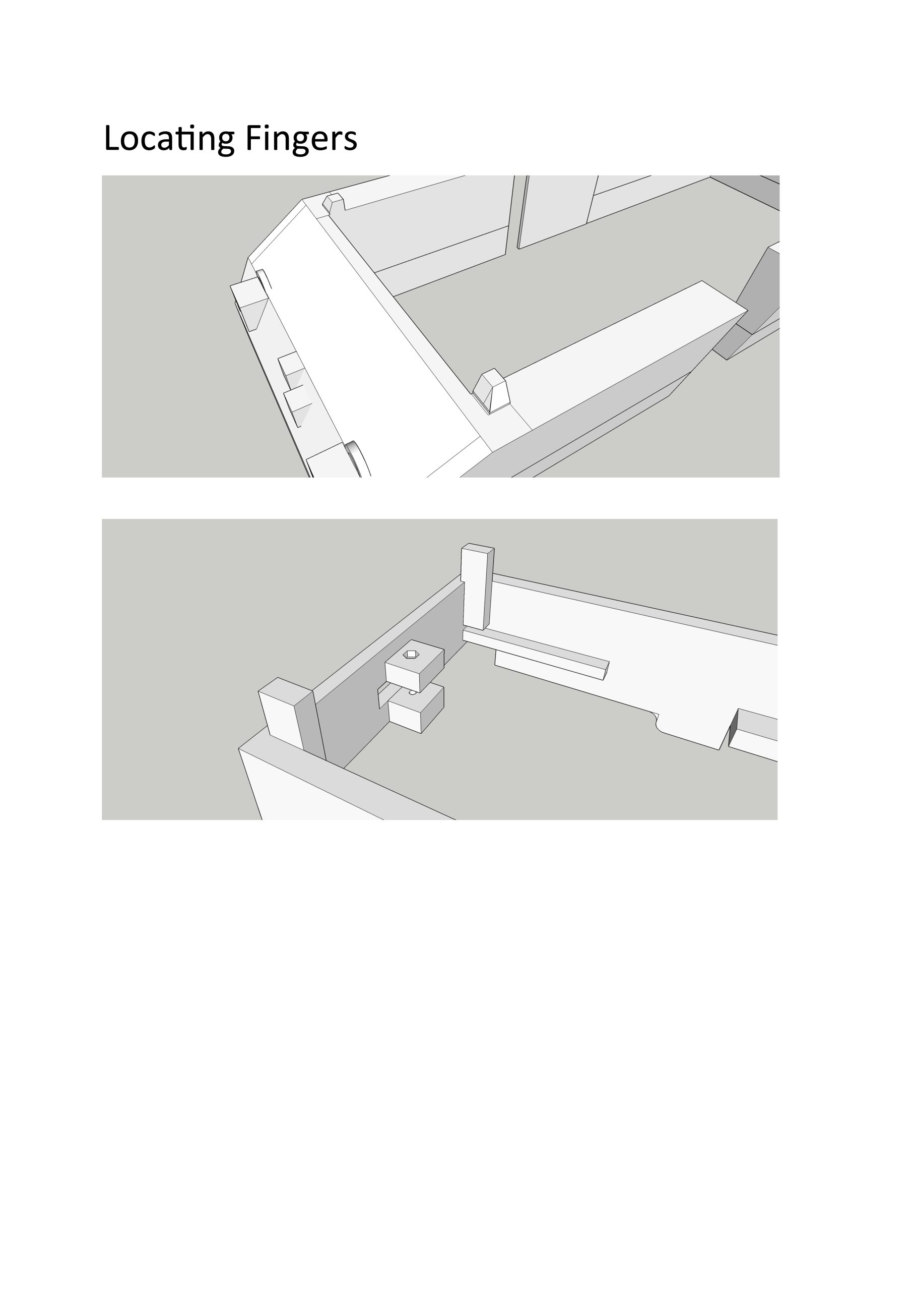
As each layer came off the printer it became apparent how useful it was to work on 4 separate layers. It made access for adding internal electronics and any other gubbins very easy, and if I decided a layer could be improved upon then I didn’t have to throw the whole model away. I pondered about having some form of locating “fingers” to ensure that the layers aligned themselves properly, and these were duly added to the design. Magnets were also considered to hold the whole thing together, but I wasn’t (and still aren’t) completely convinced by this concept.
At this stage it might help the reader visualise what’s going on if I list the 4 Layers of the loco:
Layer 1 – The roof, carrying the rotating turret.
Layer 2 – The upper hull with viewing slits and gun ports for small arms fire.
Layer 3 – The lower hull with crew access doors on either side, headlamps and grills.
Layer 4 – The skirt surrounding the motorised chassis with more grills, rivets and coupling socket.
Looking at the motorised Swift 16 chassis, I decided to make a “mantle” that sat over the chassis and had 4 holes for bolts that would screw it into layer number 4 (the bottom layer of the loco). At this point Alan produced the battery pack he proposed to use in the loco… a 10 cell AA pack from Strikalite producing 12v and 2.3 amp hours, probably enough for around 2 hours of running.
We decided to sit the pack upright across the centre of the loco as here it would give the loco a good centre of gravity. I designed a housing to hold the pack and considered how this should be fixed inside the loco. I like everything to come apart for maintenance and potential upgrading, so the use of nuts and cheese head screws always appeals to me.
At this point I realised that I could glue the battery housing to Layer number 3 and incorporate the nuts that would fix the Swift 16 chassis in place… a win-win result, allowing just 4 screws to fix the Swift 16 motorised chassis through Layer No 4 into Layer No 3, sandwiching the whole 3 layer assembly as one unit. This approach produced an elegant, practical result. Some thought was given to getting the correct ride height above that rails, so the screws passed though spacers that could be replaced as required to achieve the correct ride height.
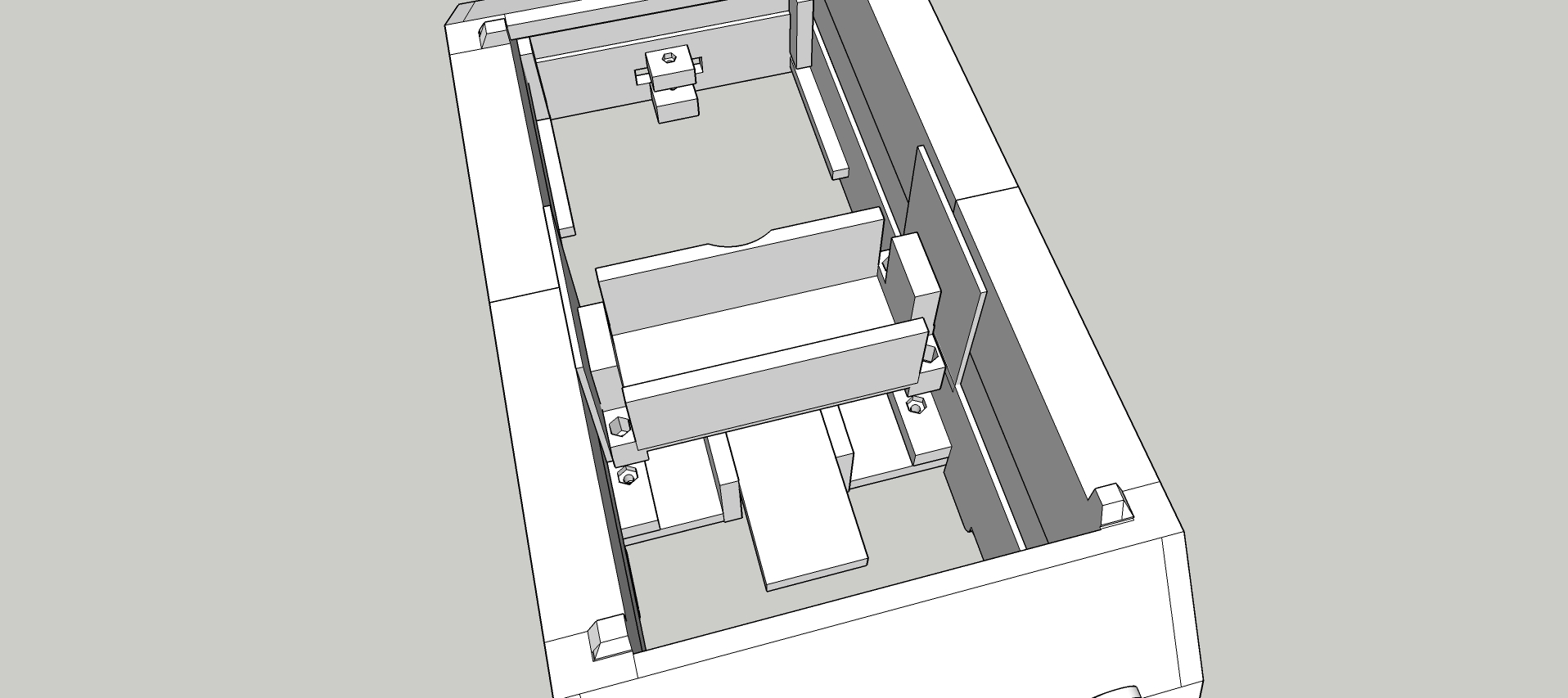
Layer 2 was stacked on top of the combined Chassis / Layer 4 / Layer 3 and was held in place by “locating fingers” and gravity. I decided that I’d keep this layer removable to get at the battery for recharging and for access to the switches that would turn the loco on and operate the lights and sound system. At the point of writing, I still haven’t decided if I need to add small magnets to secure this layer.
The sound system was also inherited from Alan. It’s just a PC card with a chip holding a suitable sound file of a multi-cylinder diesel engine that plays in a loop. It’s quite loud!
At this point the loco layers were stacked upon each other, the openings masked off and several layers of grey high-build plastic primer sprayed over the model. The result looked quite acceptable and some short running trials showed that the loco ran as well as it looked.
(See YouTube video https://youtu.be/wPU6rRPTZQo )
The next stage was adding lighting to front and rear. I’d left some 8mm dia holes in the headlamp positions intending to use these for bi-colour LEDs of an appropriate size. I spotted some suitable Warm White / Red bi-coloured LEDS on the R C Trains stand at the Elsecar show. These were 5mm diameter so I printed a shroud to hold them which could then be inserted into the 8mm hole in the body.
The bi-colour LEDs were a bit of a mystery as they only had 2 legs for the wiring. I realised that running the current in one direction produced warm white light, and reversing the polarity produced red light. The problem was to decide what value of resistor to add to the circuit as the 2 colours ideally need 2 different values of resistor. I decided to try 400 ohms as this would suit the white but might be too high for the red. In the event, 400 ohms produced the results I needed and (so far) the LEDs haven’t expired. In fact, when I made a second loco for myself I used a 470 ohm resistor and so far it’s all looking good.
The LEDS and wiring was added to layer 3 (and I was so glad that I‘d kept the layers separable, it made the installation and soldering so much easier… or rather, less hard).
The orientation of the LEDs in the circuit is shown in diagram 1 and was as follows:
Battery + to LED 1 –
LED1 + to LED 2 – (to light one end of the loco white)
LED 2 + To LED3 + (to light the other end of the loco red)
LED 3 – to LED 4 + (to add the second red light)
LED4 – via 400 ohm resistor to battery –
Probably easier done than explained!
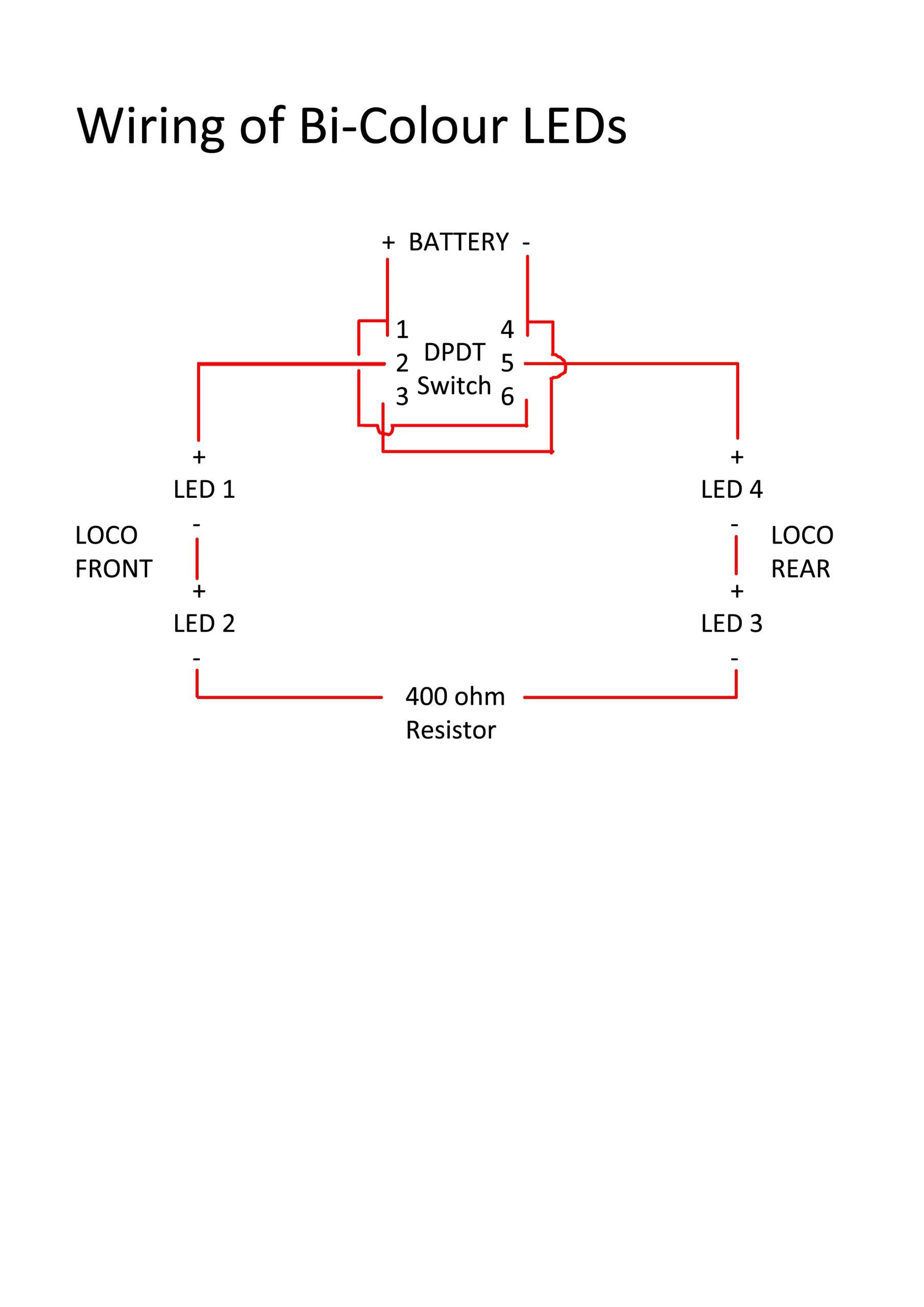
In the diagram I’ve shown the resistor to be between LEDs 2 and 3, but it doesn’t matter where it goes in the circuit. It will have the same effect.
By using a DPDT switch the direction of current through the circuit could be reversed, allowing each end of the loco to show white or red lights as required for the direction of travel.
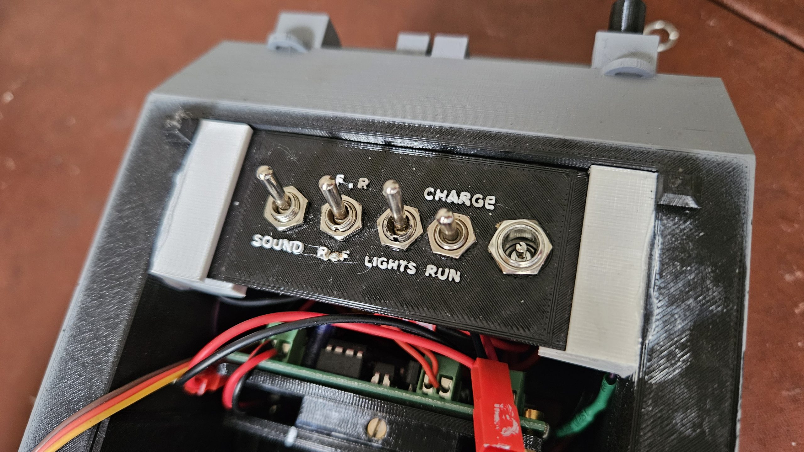
I decided to make a nice panel to hold all the switches and charging socket and this slotted into Layer 3. Just slotting it in allows it to be removed for access to the wiring, which by now was getting quite spaghetti-like.
Initially I’d hoped to have the turret radio controlled so it would revolve, but the limitations of Alan’s radio control system precluded an easy solution to this challenge. At present the turret can be turned manually, but the roof (Layer 1) has not been glued in place to allow for possible further developments in this matter.
The last stage in proceedings was to re-visit some of the layer stacking gaps, as a bit of warping / shrinkage had taken place during printing and left gaps that I was unhappy with.
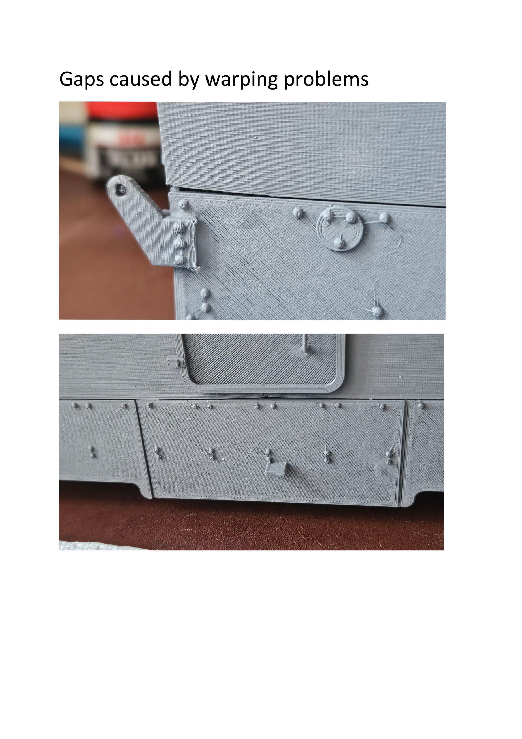
I am a great fan of Perfect Plastic Putty. This comes in a tube and is applied like any other filler. It sticks like the proverbial, dries quickly and is still flexible when dry. Applying it between the layers of the model at this stage means that these layers might not be separable in future, but this doesn’t matter much once the construction of the model is finished.
Having smoothed the filler into the offending gaps, it can be further smoothed down and any excess removed by the application of a damp (wet with water!) paintbrush.
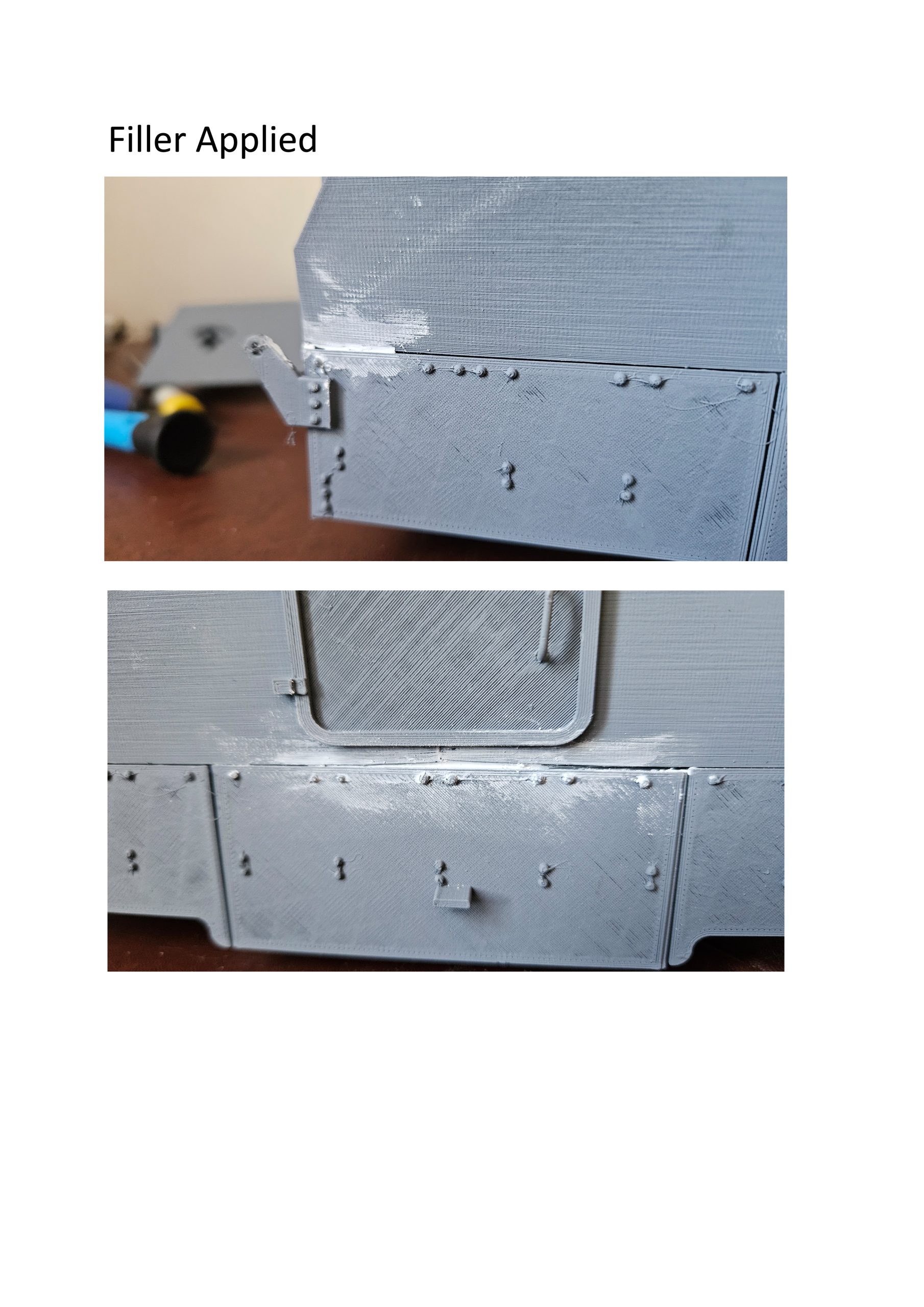
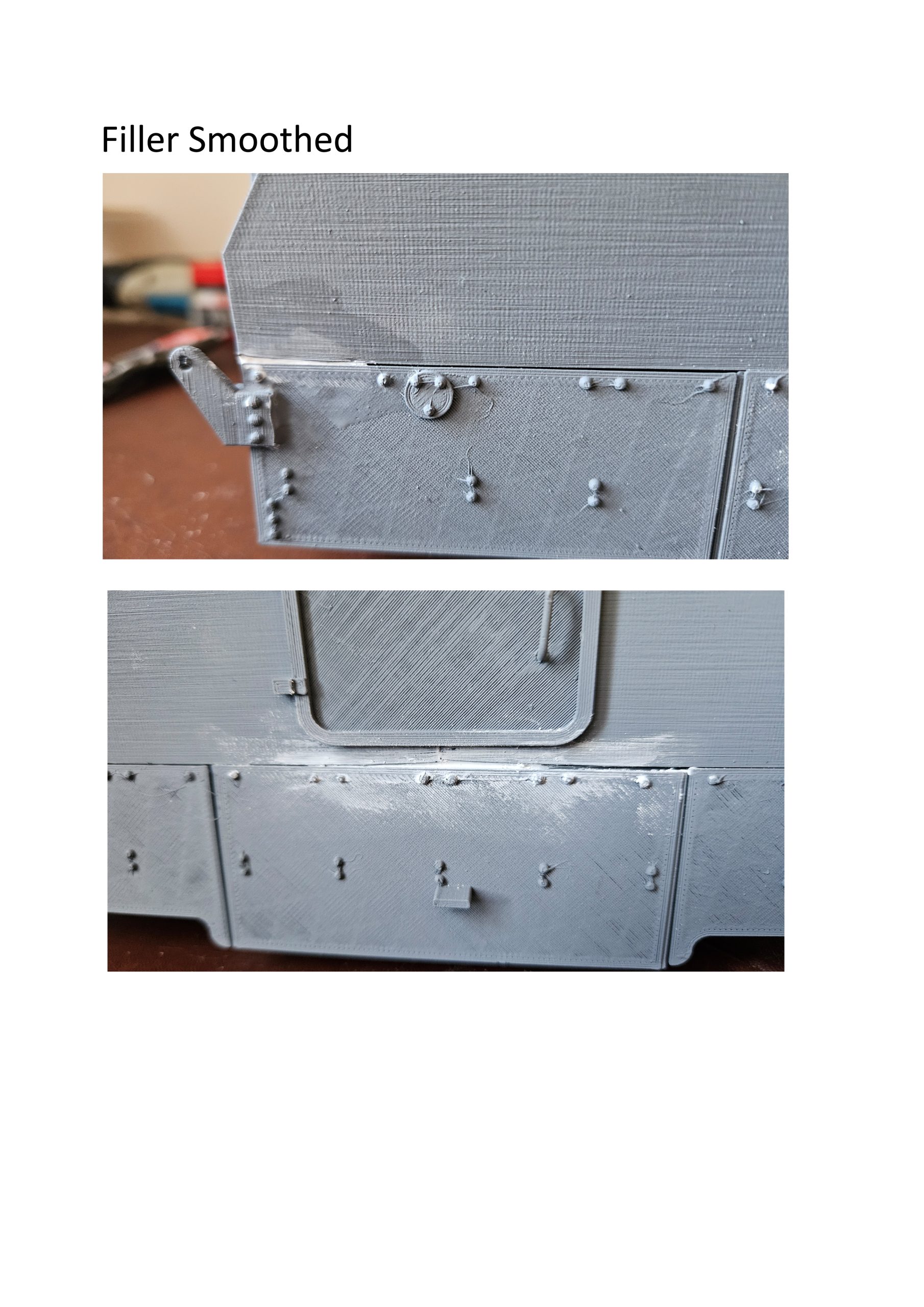
The last job was to mask the LED headlights off and give the completed model a final spray of grey high-build primer.
Et voila! We are now ready for any insurgency that might occur on our garden railways.
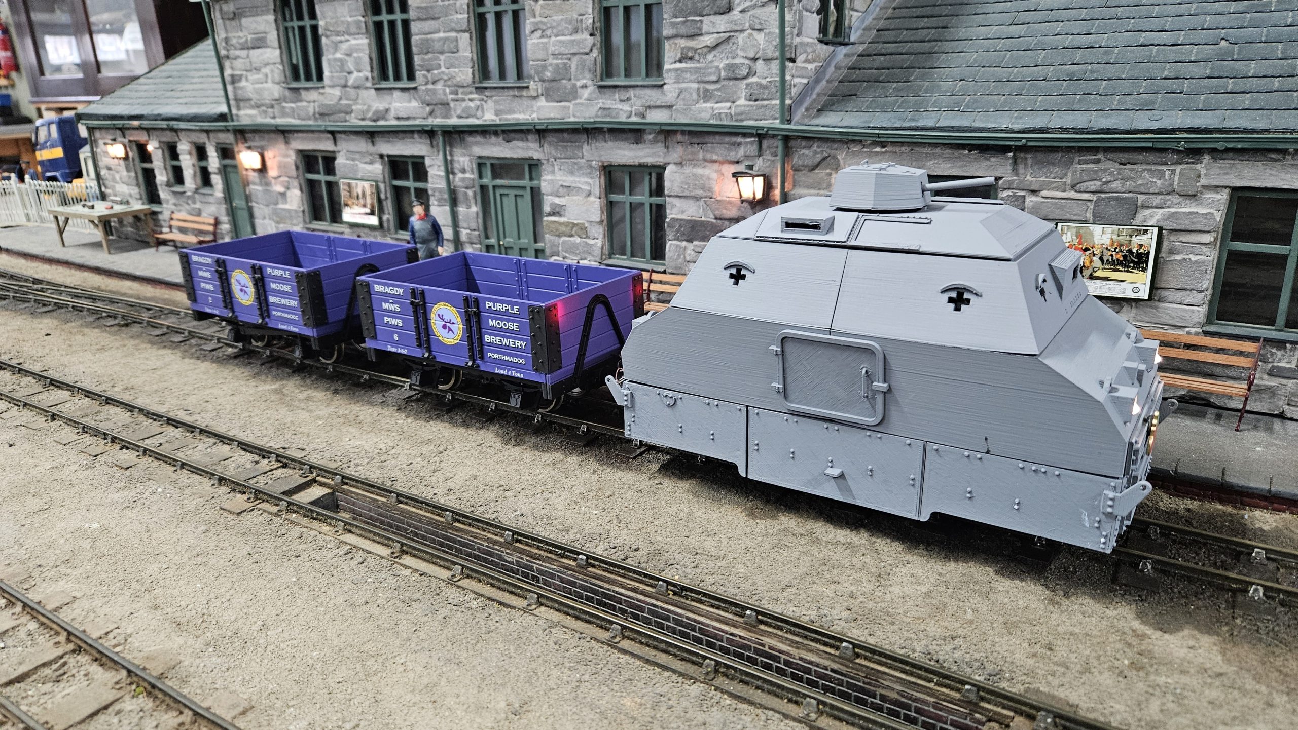
I understand that the real locos never hauled a train. The couplings were just so that one loco could rescue a second loco and for shunting dead locos around. I, however, can’t resist using the loco to head a short train!
POSTSCRIPT
Having completed Alan’s Wickham, I decided to go the whole hog and make one for myself. I went for a standard model aircraft type radio system as this would allow me to have forward and reverse on one stick and turret rotation on the other. The Swift 16 powered chassis seems to be no longer available, so I also opted for a powered chassis from Essel Engineering. Their “Power Bogie” was slightly shorter in the wheelbase that the Swift 16 chassis used on Alan’s loco, but it had the advantage of being easily gauge adjustable (which the Swift 16 chassis isn’t) and this is a feature that I wanted.
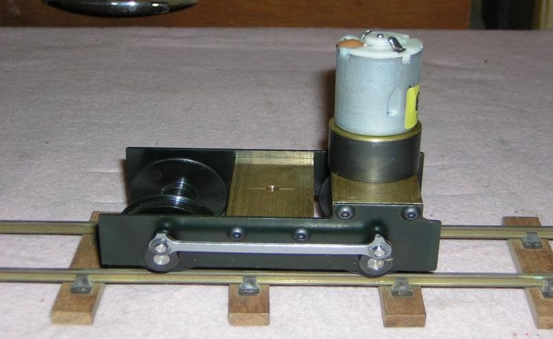
Utilising the Essel bogie required a bit of a re-design of the chassis of the model, but this is no problem if you’re designing and 3d printing your own loco. The Essel chassis uses coupling rods to link the 2 axles, but as they would be hidden under the loco’s skirts this was not an issue.
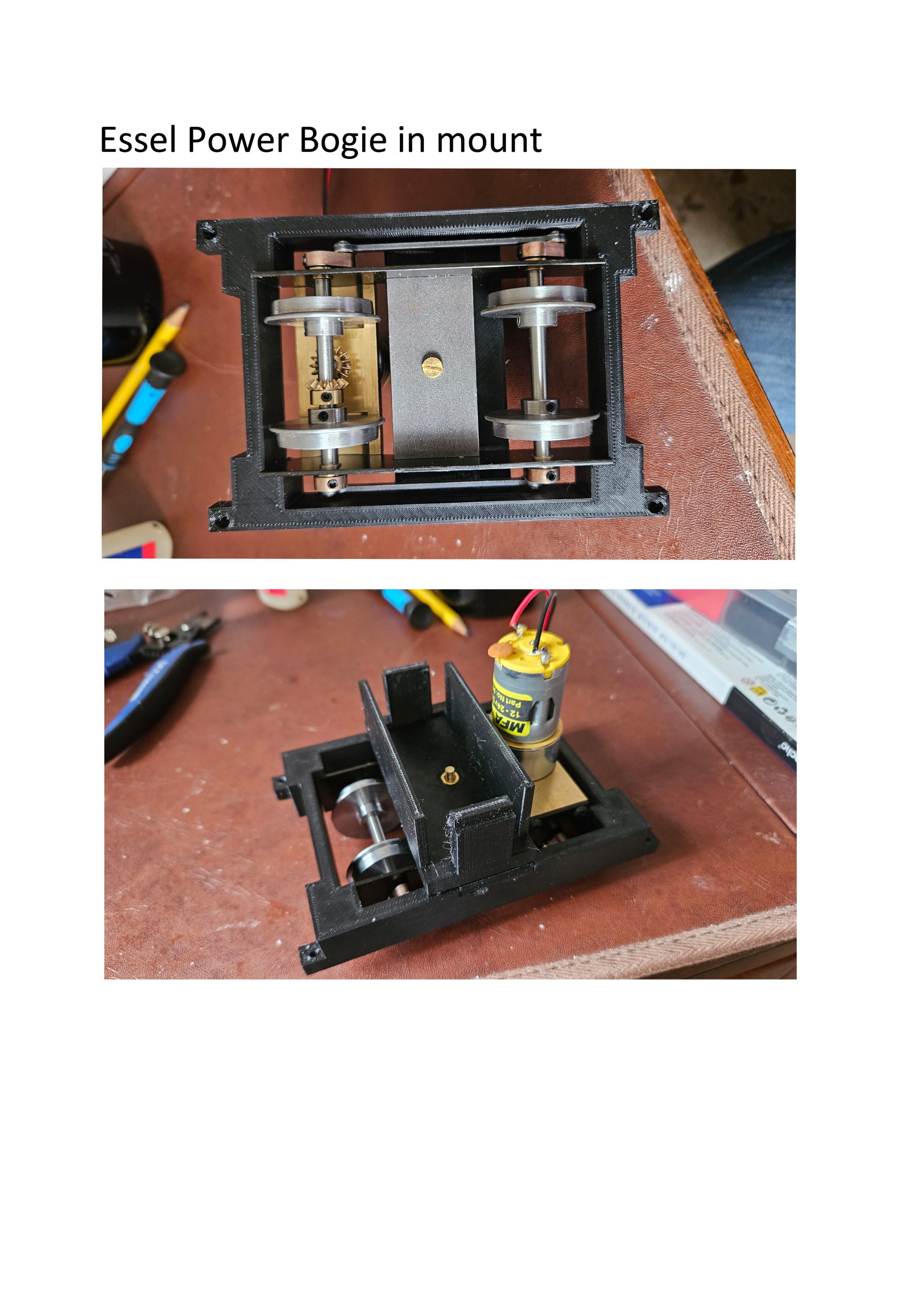
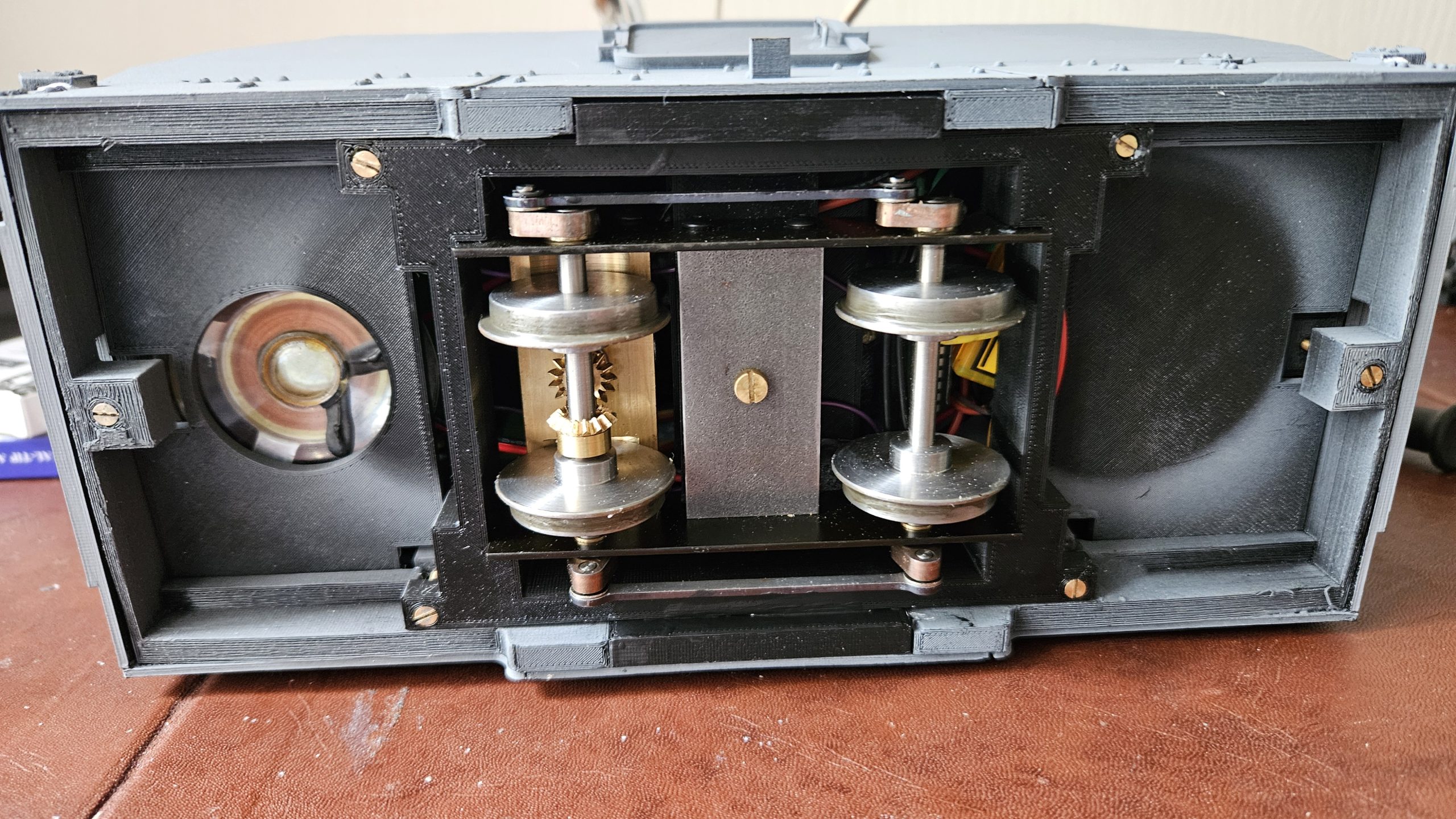
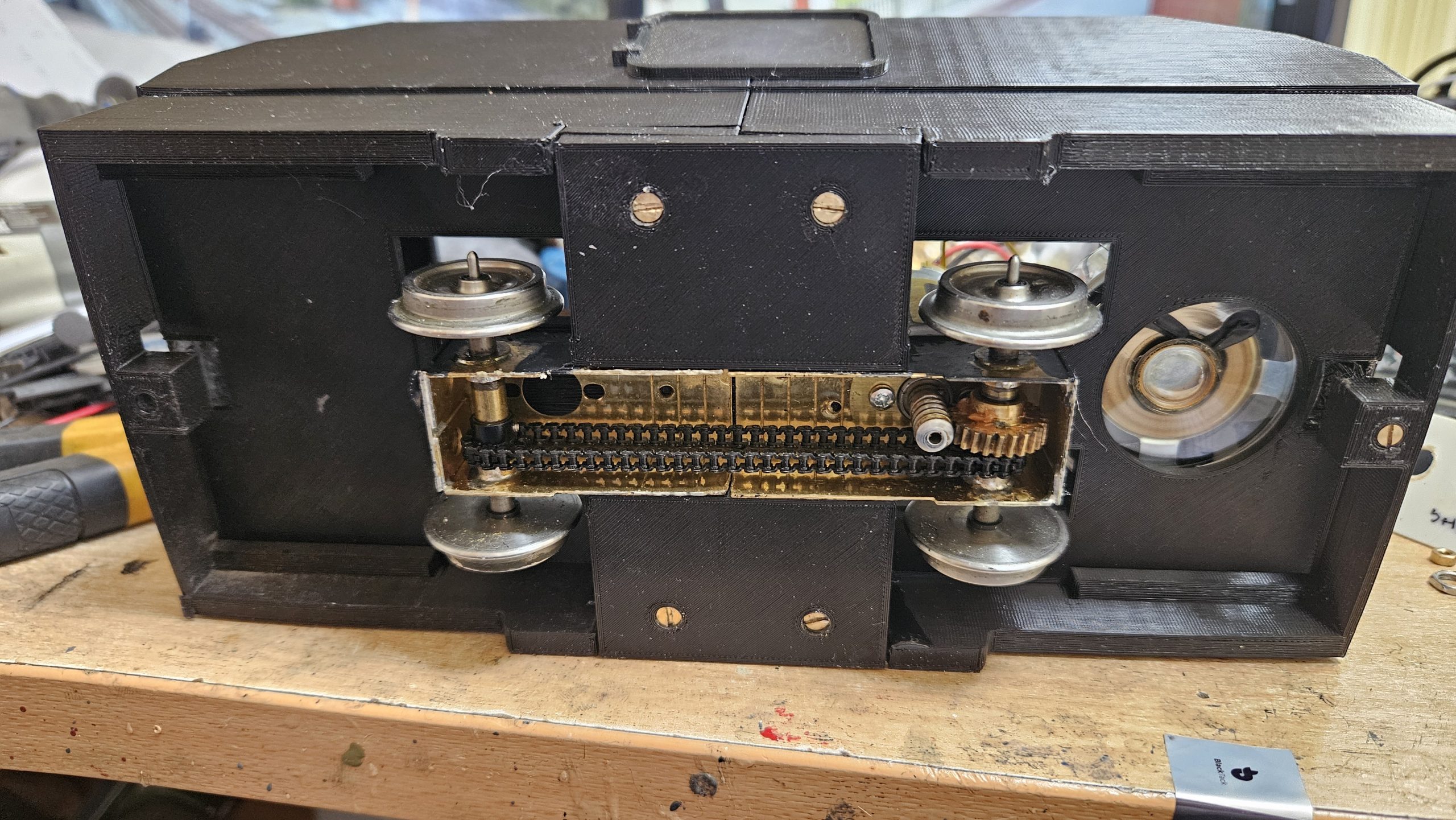
So, there we have it…. 2 armoured Wickham trollies with slightly differing power units hidden under the skirts!
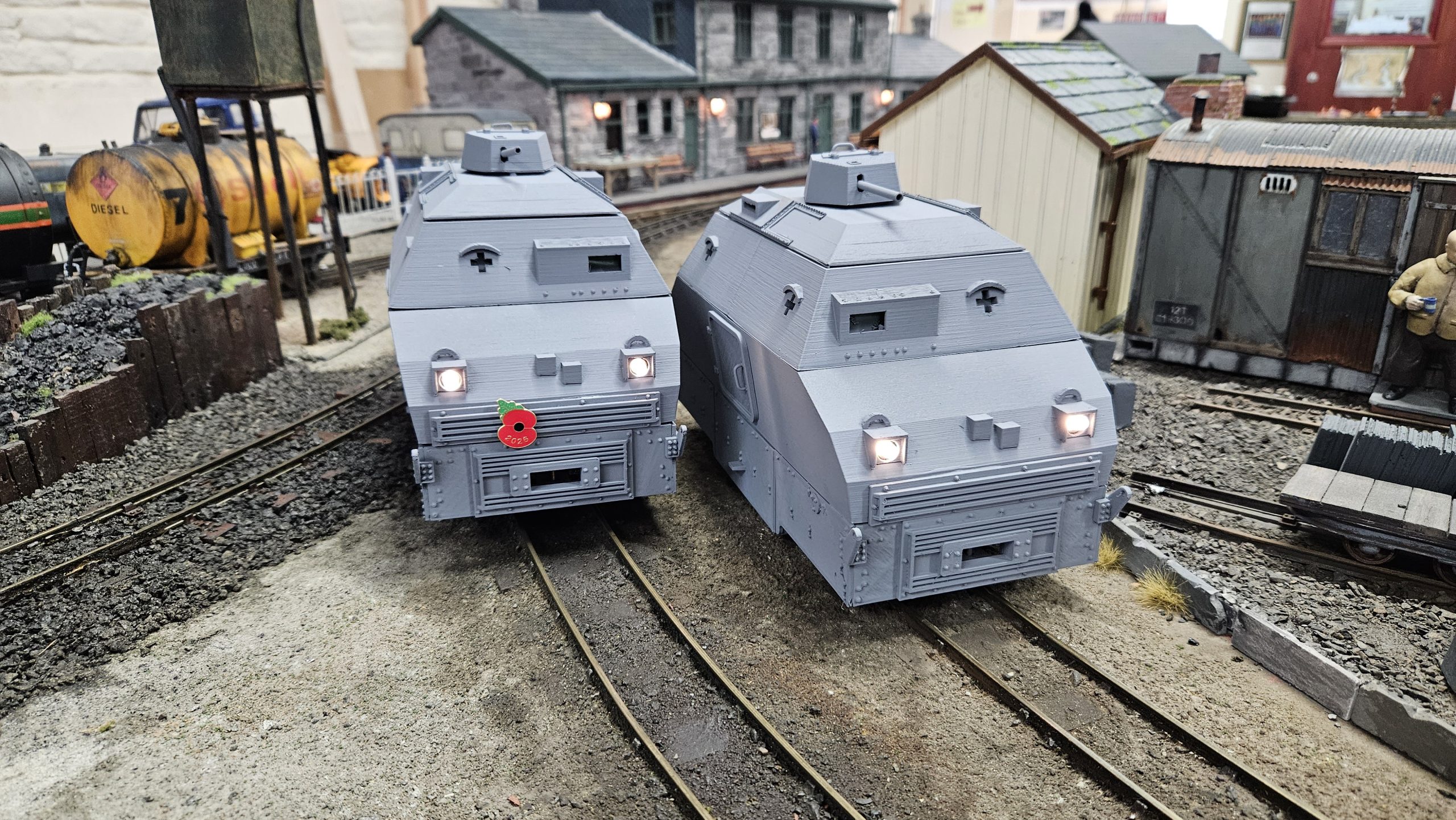
I now await the next obscure loco that Alan manages to find for me to model.
Roy Plum November 2026
with thanks to Huddersfield Railway Modellers